
Datasheet


Section 12 8-Bit Timers
Rev. 4.00 Sep 27, 2006 page 343 of 1130
REJ09B0327-0400
12.1.3 Pin Configuration
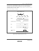
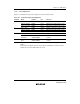
Table 12.1 summarizes the input and output pins of the 8-bit timer module.
Table 12.1 8-Bit Timer Input and Output Pins
Channel Name Symbol
*
I/O Function
0 Timer output TMO0 Output Output controlled by compare-match
Timer clock input TMCI0 Input External clock input for the counter
Timer reset input TMRI0 Input External reset input for the counter
1 Timer output TMO1 Output Output controlled by compare-match
Timer clock input TMCI1 Input External clock input for the counter
Timer reset input TMRI1 Input External reset input for the counter
X Timer output TMOX Output Output controlled by compare-match
Timer clock/
reset input
HFBACKI/TMIX
(TMCIX/TMRIX)
Input External clock/reset input for the
counter
Y Timer clock/reset
input
VSYNCI/TMIY
(TMCIY/TMRIY)
Input External clock/reset input for the
counter
Note: * The abbreviations TMO, TMCI, and TMRI are used in the text, omitting the channel
number.
Channel X and Y I/O pins have the same internal configuration as channels 0 and 1,
and therefore the same abbreviations are used.