
Datasheet

Section 13 Timer Connection
Rev. 4.00 Sep 27, 2006 page 377 of 1130
REJ09B0327-0400
Section 13 Timer Connection
Provided in the H8S/2148 Group; not provided in the H8S/2144 Group and H8S/2147N.
13.1 Overview
The H8S/2148 Group allows interconnection between a combination of input signals, the
input/output of the single free-running timer (FRT) channel and the three 8-bit timer channels
(TMR1, TMRX, and TMRY). This capability can be used to implement complex functions such as
PWM decoding and clamp waveform output. All the timers are initially set for independent
operation.
13.1.1 Features
The features of the timer connection facility are as follows.
• Five input pins and four output pins, all of which can be designated for phase inversion.
Positive logic is assumed for all signals used within the timer connection facility.
• An edge-detection circuit is connected to the input pins, simplifying signal input detection.
• TMRX can be used for PWM input signal decoding and clamp waveform generation.
• An external clock signal divided by TMR1 can be used as the FRT capture input signal.
• An internal synchronization signal can be generated using the FRT and TMRY.
• A signal generated/modified using an input signal and timer connection can be selected and
output.
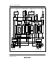
13.1.2 Block Diagram
Figure 13.1 shows a block diagram of the timer connection facility.