
Datasheet

Section 13 Timer Connection
Rev. 4.00 Sep 27, 2006 page 381 of 1130
REJ09B0327-0400
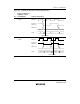
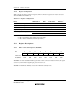
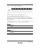
Bits 7 and 6—Input Synchronization Mode Select 1 and 0 (SIMOD1, SIMOD0): These bits
select the signal source of the IHI and IVI signals.
Bit 7 Bit 6 Description
SIMOD1 SIMOD0 Mode IHI Signal IVI Signal
0 0 No signal (Initial value) HFBACKI input VFBACKI input
1 S-on-G mode CSYNCI input PDC input
1 0 Composite mode HSYNCI input PDC input
1 Separate mode HSYNCI input VSYNCI input
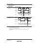
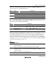
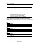
Bit 5—Synchronization Signal Connection Enable (SCONE): Selects the signal source of the
FRT FTI input and the TMR1 TMCI1/TMRI1 input.
Bit 5 Description
SCONE Mode FTIA FTIB FTIC FTID TMCI1 TMRI1
0 Normal connection (Initial value) FTIA
input
FTIB
input
FTIC
input
FTID
input
TMCI1
input
TMRI1
input
1 Synchronization signal
connection mode
IVI
signal
TMO1
signal
VFBACKI
input
IHI
signal
IHI
signal
IVI
inverse
signal
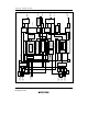
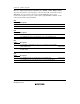
Bit 4—Input Capture Start Bit (ICST): The TMRX external reset input (TMRIX) is connected
to the IHI signal. TMRX has input capture registers (TICR, TICRR, and TICRF). TICRR and
TICRF can measure the width of a short pulse by means of a single capture operation under the
control of the ICST bit. When a rising edge followed by a falling edge is detected on TMRIX after
the ICST bit is set to 1, the contents of TCNT at those points are captured into TICRR and TICRF,
respectively, and the ICST bit is cleared to 0.
Bit 4
ICST Description
0 The TICRR and TICRF input capture functions are stopped (Initial value)
[Clearing condition]
When a rising edge followed by a falling edge is detected on TMRIX
1 The TICRR and TICRF input capture functions are operating
(Waiting for detection of a rising edge followed by a falling edge on TMRIX)
[Setting condition]
When 1 is written in ICST after reading ICST = 0