
Datasheet

Section 13 Timer Connection
Rev. 4.00 Sep 27, 2006 page 391 of 1130
REJ09B0327-0400
MSTPCRH Bit 4—Module Stop (MSTP12): Specifies 8-bit timer channel 0 and 1 module stop
mode.
MSTPCRH
Bit 4
MSTP12 Description
0 8-bit timer channel 0 and 1 module stop mode is cleared
1 8-bit timer channel 0 and 1 module stop mode is set (Initial value)
MSTPCRH Bit 0—Module Stop (MSTP8): Specifies 8-bit timer channel X and Y and timer
connection module stop mode.
MSTPCRH
Bit 0
MSTP8 Description
0 8-bit timer channel X and Y and timer connection module stop mode is cleared
1 8-bit timer channel X and Y and timer connection module stop mode is
set
(Initial value)
13.3 Operation
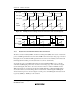
13.3.1 PWM Decoding (PDC Signal Generation)
The timer connection facility and TMRX can be used to decode a PWM signal in which 0 and 1
are represented by the pulse width. To do this, a signal in which a rising edge is generated at
regular intervals must be selected as the IHI signal.
The timer counter (TCNT) in TMRX is set to count the internal clock pulses and to be cleared on
the rising edge of the external reset signal (IHI signal). The value to be used as the threshold for
deciding the pulse width is written in TCORB. The PWM decoder contains a delay latch which
uses the IHI signal as data and compare-match signal B (CMB) as a clock, and the state of the IHI
signal (the result of the pulse width decision) at the compare-match signal B timing after TCNT is
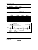
reset by the rise of the IHI signal is output as the PDC signal. The pulse width setting using
TICRR and TICRF of TMRX can be used to determine the pulse width decision threshold.
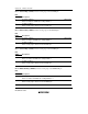
Examples of TCR and TCORB settings are shown in tables 13.3 and 13.4, and the timing chart is
shown in figure 13.2.