
Datasheet


Section 13 Timer Connection
Rev. 4.00 Sep 27, 2006 page 395 of 1130
REJ09B0327-0400
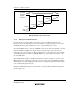
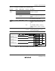
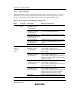
Table 13.5 Examples of TCR and TCSR Settings
Register Bit(s) Abbreviation Contents Description
TCR in TMR1 7 CMIEB 0
6CMIEA 0
5OVIE 0
Interrupts due to compare-match
and overflow are disabled
4 and 3 CCLR1, CCLR0 11 TCNT is cleared by the rising edge
of the external reset signal (inverted
IVI signal)
2 to 0 CKS2 to CKS0 101 TCNT is incremented on the rising
edge of the external clock (IHI
signal)
TCSR in TMR1 3 to 0 OS3 to OS0 0011
1001
Not changed by compare-match B;
output inverted by compare-match A
(toggle output): division by 512
or
when TCORB < TCORA, 1 output
on compare-match B, and 0 output
on compare-match A: division by
256
TCR in FRT 6 IEDGB 0/1 0: FRC value is transferred to ICRB
on falling edge of input capture
input B (IHI divided signal
waveform)
1: FRC value is transferred to ICRB
on rising edge of input capture
input B (IHI divided signal
waveform)
1 and 0 CKS1, CKS0 01 FRC is incremented on internal
clock: φ/8
TCSR in FRT 0 CCLRA 0 FRC clearing is disabled