
Datasheet


Section 14 Watchdog Timer (WDT)
Rev. 4.00 Sep 27, 2006 page 415 of 1130
REJ09B0327-0400
read-only bit. It is set to 1 by an external reset, and when the RST/NMI bit is 1, is cleared to 0 by
an internal reset due to watchdog timer overflow.
Bit 3
XRST Description
0 Reset is generated by watchdog timer overflow
1 Reset is generated by external reset input (Initial value)
14.2.4 Notes on Register Access
The watchdog timer’s TCNT and TCSR registers differ from other registers in being more difficult
to write to. The procedures for writing to and reading these registers are given below.
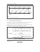
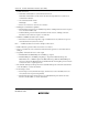
Writing to TCNT and TCSR (Example of WDT0)
These registers must be written to by a word transfer instruction. They cannot be written to with
byte transfer instructions.
Figure 14.2 shows the format of data written to TCNT and TCSR. TCNT and TCSR both have the
same write address. For a write to TCNT, the upper byte of the written word must contain H'5A
and the lower byte must contain the write data. For a write to TCSR, the upper byte of the written
word must contain H'A5 and the lower byte must contain the write data. This transfers the write
data from the lower byte to TCNT or TCSR.
TCNT write
TCSR write
Address: H'FFA8
Address: H'FFA8
H'5A Write data
15 8 7 0
H'A5 Write data
15 8 7 0
Figure 14.2 Format of Data Written to TCNT and TCSR (Example of WDT0)
Reading TCNT and TCSR (Example of WDT0)
These registers are read in the same way as other registers. The read addresses are H'FFA8 for
TCSR, and H'FFA9 for TCNT.