
Datasheet


Section 15 Serial Communication Interface (SCI, IrDA)
Rev. 4.00 Sep 27, 2006 page 477 of 1130
REJ09B0327-0400
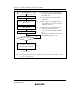
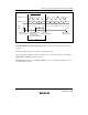
Serial Data Transmission (Synchronous Mode): Figure 15.16 shows a sample flowchart for
serial transmission.
The following procedure should be used for serial data transmission.
No
<End>
[1]
Yes
Initialization
Start transmission
Read TDRE flag in SSR [2]
Write transmit data to TDR and
clear TDRE flag in SSR to 0
No
Yes
No
Yes
Read TEND flag in SSR
[3]
Clear TE bit in SCR to 0
TDRE = 1?
All data transmitted?
TEND = 1?
[1] SCI initialization:
The TxD pin is automatically
designated as the transmit data output
pin.
[2] SCI status check and transmit data
write:
Read SSR and check that the TDRE
flag is set to 1, then write transmit data
to TDR and clear the TDRE flag to 0.
[3] Serial transmission continuation
procedure:
To continue serial transmission, be
sure to read 1 from the TDRE flag to
confirm that writing is possible, then
write data to TDR, and then clear the
TDRE flag to 0.
Checking and clearing of the TDRE
flag is automatic when the DTC is
activated by a transmit-data-empty
interrupt (TXI) request and data is
written to TDR.
Figure 15.16 Sample Serial Transmission Flowchart