
Datasheet

Section 16 I
2
C Bus Interface [Option]
Rev. 4.00 Sep 27, 2006 page 519 of 1130
REJ09B0327-0400
Bit 5—DDC Mode Switch Interrupt Enable Bit (IE): Enables or disables an interrupt request to
the CPU when automatic format switching is executed for IIC channel 0.
Bit 5
IE Description
0 Interrupt when automatic format switching is executed is disabled (Initial value)
1 Interrupt when automatic format switching is executed is enabled
Bit 4—DDC Mode Switch Interrupt Flag (IF): Flag that indicates an interrupt request to the
CPU when automatic format switching is executed for IIC channel 0.
Bit 4
IF Description
0 No interrupt is requested when automatic format switching is executed (Initial value)
[Clearing condition]
When 0 is written in IF after reading IF = 1
1 An interrupt is requested when automatic format switching is executed
[setting condition]
When a falling edge is detected on the SCL pin when SWE = 1
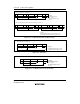
Bits 3 to 0—IIC Clear 3 to 0 (CLR3 to CLR0): These bits control initialization of the internal
state of IIC0 and IIC1.
These bits can only be written to; if read they will always return a value of 1.
When a write operation is performed on these bits, a clear signal is generated for the internal latch
circuit of the corresponding module(s), and the internal state of the IIC module(s) is initialized.
The write data for these bits is not retained. To perform IIC clearance, bits CLR3 to CLR0 must be
written to simultaneously using an MOV instruction. Do not use a bit-manipulation instruction
such as BCLR.
When clearing is required again, all the bits must be written to in accordance with the setting.