
Datasheet

Section 16 I
2
C Bus Interface [Option]
Rev. 4.00 Sep 27, 2006 page 520 of 1130
REJ09B0327-0400
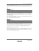
Bit 3 Bit 2 Bit 1 Bit 0
CLR3 CLR2 CLR1 CLR0 Description
00——Setting prohibited
1 0 0 Setting prohibited
1 IIC0 internal latch cleared
1 0 IIC1 internal latch cleared
1 IIC0 and IIC1 internal latches cleared
1 ———Invalid setting
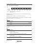
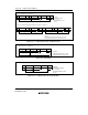
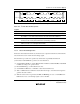
16.2.9 Module Stop Control Register (MSTPCR)
7
MSTP15
0
R/W
Bit
Initial value
Read/Write
6
MSTP14
0
R/W
5
MSTP13
1
R/W
4
MSTP12
1
R/W
3
MSTP11
1
R/W
2
MSTP10
1
R/W
1
MSTP9
1
R/W
0
MSTP8
1
R/W
7
MSTP7
1
R/W
6
MSTP6
1
R/W
5
MSTP5
1
R/W
4
MSTP4
1
R/W
3
MSTP3
1
R/W
2
MSTP2
1
R/W
1
MSTP1
1
R/W
0
MSTP0
1
R/W
MSTPCRH MSTPCRL
MSTPCR comprises two 8-bit readable/writable registers, and is used to perform module stop
mode control.
When the MSTP4 or MSTP3 bit is set to 1, operation of the corresponding IIC channel is halted at
the end of the bus cycle, and a transition is made to module stop mode. For details, see section
25.5, Module Stop Mode.
MSTPCR is initialized to H'3FFF by a reset and in hardware standby mode. It is not initialized in
software standby mode.
MSTPCRL Bit 4—Module Stop (MSTP4): Specifies IIC channel 0 module stop mode.
MSTPCRL
Bit 4
MSTP4 Description
0 IIC channel 0 module stop mode is cleared
1 IIC channel 0 module stop mode is set (Initial value)