
Datasheet

Section 16 I
2
C Bus Interface [Option]
Rev. 4.00 Sep 27, 2006 page 524 of 1130
REJ09B0327-0400
(6) Write data to ICDR (slave address + R/W)
With the I
2
C bus format (when the FS bit in SAR or the FSX bit in SARX is 0), the first frame
data following the start condition indicates the 7-bit slave address and transmit/receive
direction.
Then clear the IRIC flag to indicate the end of transfer.
Writing to ICDR and clearing of the IRIC flag must be executed continuously, so that no
interrupt is inserted.
If a period of time that is equal to transfer one byte has elapsed by the time the IRlC flag is
cleared, the end of transfer cannot be identified.
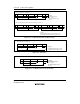
The master device sequentially sends the transmit clock and the data written to ICDR with the
timing shown in figure 16.7. The selected slave device (i.e., the slave device with the
matching slave address) drives SDA low at the 9th transmit clock pulse and returns an
acknowledge signal.
(7) When one frame of data has been transmitted, the IRIC flag is set to 1 at the rise of the 9th
transmit clock pulse. After one frame has been transmitted, SCL is automatically fixed low in
synchronization with the internal clock until the next transmit data is written.
(8) Read the ACKB bit to confirm that ACKB is 0. When the slave device has not returned an
acknowledge signal and ACKB remains 1, execute the transmit end processing described in
step (12) and perform transmit operation again.
(9) Write the next data to be transmitted in ICDR. To indicate the end of data transfer, clear the
IRIC flag to 0.
As described in step (6) above, writing to ICDR and clearing of the IRIC flag must be
executed continuously so that no interrupt is inserted.
The next frame is transmitted in synchronization with the internal clock.
(10)When one frame of data has been transmitted, the IRIC flag is set to 1 at the rise of the 9th
transmit clock pulse. After one frame has been transmitted, SCL is automatically fixed low in
synchronization with the internal clock until the next transmit data is written.
(11)Read the ACKB bit of ICSR. Confirm that the slave device has returned an acknowledge
signal and ACKB is 0. When more data is to be transmitted, return to step (9) to execute next
transmit operation. If the slave device has not returned an acknowledge signal and ACKB is 1,
execute the transmit end processing described in step (12).
(12)Clear the IRIC flag to 0. Write BBSY and SCP of ICCR to 0. By doing so, SDA is changed
from low to high while SCL is high and the transmit stop condition is generated.