
Datasheet


Section 18 Host Interface
Rev. 4.00 Sep 27, 2006 page 597 of 1130
REJ09B0327-0400
18.3.2 Control States
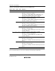
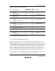
Table 18.5 shows host interface operations from the HIF host, and slave operation.
Table 18.5 Host Interface Operations from HIF Host, and Slave Operation
Other than
CSn
CSnCSn
CSn CSn
CSnCSn
CSn IOR
IORIOR
IOR IOW
IOWIOW
IOW HA0 Operation
1 0000Setting prohibited
1 Setting prohibited
1 0 Data read from output data register n (ODRn)
1 Status read from status register n (STRn)
1 0 0 Data written to input data register n (IDRn)
1 Command written to input data register n (IDRn)
10Idle state
1 Idle state
Note: n = 1 to 4
18.3.3 A20 Gate
The A20 gate signal can mask address A20 to emulate an addressing mode used by personal
computers with an 8086
*
-family CPU. In slave mode, a regular-speed A20 gate signal can be
output under firmware control. Fast A20 gate output is enabled by setting the FGA20E bit (bit 0)
to 1 in HICR (H'FFF0).
Note: * Intel microprocessor.
Regular A20 Gate Operation
Output of the A20 gate signal can be controlled by an H'D1 command followed by data. When the
slave processor receives data, it normally uses an interrupt routine activated by the IBF1 interrupt
to read IDR1. If the data follows an H'D1 command, software copies bit 1 of the data and outputs
it at the gate A20 pin.
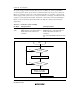
Fast A20 Gate Operation
When the FGA20E bit is set to 1, P81/GA20 is used for output of a fast A20 gate signal. Bit
P81DDR must be set to 1 to assign this pin for output. The initial output from this pin will be a
logic 1, which is the initial value. Afterward, the host processor can manipulate the output from