
Datasheet
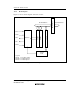

Section 19 D/A Converter
Rev. 4.00 Sep 27, 2006 page 608 of 1130
REJ09B0327-0400
19.2 Register Descriptions
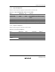
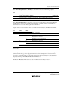
19.2.1 D/A Data Registers 0 and 1 (DADR0, DADR1)
Bit
Initial value
Read/Write
7
0
R/W
6
0
R/W
5
0
R/W
4
0
R/W
3
0
R/W
0
0
R/W
2
0
R/W
1
0
R/W
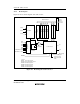
D/A data registers 0 and 1 (DADR0 and DADR1) are 8-bit readable/writable registers that store
data to be converted. When analog output is enabled, the value in the D/A data register is
converted and output continuously at the analog output pin.
The D/A data registers are initialized to H'00 by a reset and in hardware standby mode.
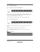
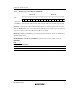
19.2.2 D/A Control Register (DACR)
Bit
Initial value
Read/Write
7
DAOE1
0
R/W
6
DAOE0
0
R/W
5
DAE
0
R/W
4
—
1
—
3
—
1
—
0
—
1
—
2
—
1
—
1
—
1
—
DACR is an 8-bit readable/writable register that controls the operation of the D/A converter
module.
DACR is initialized to H'1F by a reset and in hardware standby mode.
Bit 7—D/A Output Enable 1 (DAOE1): Controls D/A conversion and analog output.
Bit 7
DAOE1 Description
0 Analog output DA1 is disabled (Initial value)
1 D/A conversion is enabled on channel 1. Analog output DA1 is enabled