
Datasheet

Section 23 ROM (H8S/2148 F-ZTAT A-Mask Version, H8S/2147 F-ZTAT A-Mask Version, H8S/2144 F-ZTAT A-Mask Version)
Rev. 4.00 Sep 27, 2006 page 705 of 1130
REJ09B0327-0400
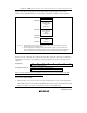
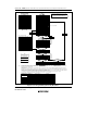
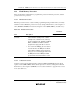
Figure 23.10. The boot program area can be used when the programming control program
transferred into the RAM enters the execution state. A stack area should be set up as required.
H'(FF)E080
H'(FF)E088
H'(FF)EFFF
H'(FF)E880
Programming
control program
area
*
1
(2040 bytes)
ID code area
*
1
H'(FF)FF00
H'(FF)FF7F
Boot program
area
*
2
(128 bytes)
Boot program
area
*
2
(1920 bytes)
Notes: 1. In the 64-kbyte version, this is a reserved area that is used only during the boot mode.
Do not use this area for other purposes.
2. The boot program area cannot be used until a transition is made to the execution state
for the programming control program transferred to the RAM. Note that the boot program
remains stored in this area after a branch is made to the programming control program.
Figure 23.10 RAM Areas in Boot Mode
In the boot mode of this chip, the content in the 8-byte ID code area shown below is confirmed so
that whether or not there is a programming control program that corresponds to the chip can be
checked.
H'(FF)E080 40 FE 64 66 32 31 34 39
↑ (product identification ID)
H'(FF)E088 and above Instruction code for write control program
When a new programming control program for use in boot mode is created, add the 8-byte ID
code described above to the head of the program.
Notes on Use of Boot Mode
• When the chip comes out of reset in boot mode, it measures the low period of the input at the
SCI’s RxD1 pin. The reset should end with RxD1 high. After the reset ends, it takes about 100
states for the chip to get ready to measure the low period of the RxD1 input.