
Datasheet

Section 23 ROM (H8S/2148 F-ZTAT A-Mask Version, H8S/2147 F-ZTAT A-Mask Version, H8S/2144 F-ZTAT A-Mask Version)
Rev. 4.00 Sep 27, 2006 page 706 of 1130
REJ09B0327-0400
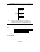
• In boot mode, if any data has been programmed into the flash memory (if all data is not 1), all
flash memory blocks are erased. Boot mode is for use when user program mode is unavailable,
such as the first time on-board programming is performed, or if the program activated in user
program mode is accidentally erased.
• Interrupts cannot be used while the flash memory is being programmed or erased.
• The RxD1 and TxD1 pins should be pulled up on the board.
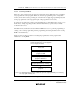
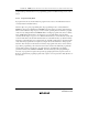
• Before branching to the programming control program (RAM area H'(FF)E088), the chip
terminates transmit and receive operations by the on-chip SCI (channel 1) (by clearing the RE
and TE bits in SCR to 0), but the adjusted bit rate value remains set in BRR. The transmit data
output pin, TxD1, goes to the high-level output state (P84DDR = 1, P84DR = 1).
The contents of the CPU’s internal general registers are undefined at this time, so these
registers must be initialized immediately after branching to the programming control program.
In particular, since the stack pointer (SP) is used implicitly in subroutine calls, etc., a stack area
must be specified for use by the programming control program.
The initial values of other on-chip registers are not changed.
• Boot mode can be entered by making the pin settings shown in table 23.6 and executing a
reset-start.
When the chip detects the boot mode setting at reset release
*
1
, P92, P91, and P90 can be used
as I/O ports.
Boot mode can be cleared by driving the reset pin low, waiting at least 20 states, then setting
the mode pins, and executing reset release
*
1
. Boot mode can also be cleared by a WDT
overflow reset. The mode pin input levels must not be changed in boot mode.
• If the mode pin input levels are changed (for example, from low to high) during a reset, the
state of ports with multiplexed address functions and bus control output pins (AS, RD, HWR)
will change according to the change in the microcomputer’s operating mode
*
2
.
Therefore, care must be taken to make pin settings to prevent these pins from becoming output
signal pins during a reset, or to prevent collision with signals outside the microcomputer.
Notes: 1. Mode pins input must satisfy the mode programming setup time (t
MDS
= 4 states) with
respect to the reset release timing.
2. Ports with multiplexed address functions will output a low level as the address signal if
mode pin setting is for mode 1 is entered during a reset. In other modes, the port pins
go to the high-impedance state. The bus control output signals will output a high level
if mode pin setting is for mode 1 is entered during a reset. In other modes, the port pins
go to the high-impedance state.