
Datasheet


Section 23 ROM (H8S/2148 F-ZTAT A-Mask Version, H8S/2147 F-ZTAT A-Mask Version, H8S/2144 F-ZTAT A-Mask Version)
Rev. 4.00 Sep 27, 2006 page 719 of 1130
REJ09B0327-0400
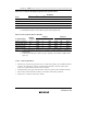
Table 23.11 Settings for Each Operating Mode in Programmer Mode
Pin Names
Mode CE
CECE
CE OE
OEOE
OE WE
WEWE
WE FO0 to FO7 FA0 to FA17
Read L L H Data output Ain
Output disable L H H Hi-Z X
Command write L H L Data input Ain
*
2
Chip disable
*
1
HXXHi-Z X
Notes: 1. Chip disable is not a standby state; internally, it is an operation state.
2. Ain indicates that there is also address input in auto-program mode.
Table 23.12 Programmer Mode Commands
1st Cycle 2nd Cycle
Command Name
Number
of Cycles
Mode Address Data Mode Address Data
Memory read mode 1 + n Write X H'00 Read RA Dout
Auto-program mode 129 Write X H'40 Write WA Din
Auto-erase mode 2 Write X H'20 Write X H'20
Status read mode 2 Write X H'71 Write X H'71
Notes: 1. In auto-program mode. 129 cycles are required for command writing by a simultaneous
128-byte write.
2. In memory read mode, the number of cycles depends on the number of address write
cycles (n).
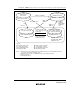
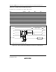
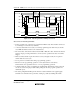
23.10.4 Memory Read Mode
• After the end of an auto-program, auto-erase, or status read operation, the command wait state
is entered. To read memory contents, a transition must be made to memory read mode by
means of a command write before the read is executed.
• Command writes can be performed in memory read mode, just as in the command wait state.
• Once memory read mode has been entered, consecutive reads can be performed.
• After power-on, memory read mode is entered.