
Datasheet


Section 23 ROM (H8S/2148 F-ZTAT A-Mask Version, H8S/2147 F-ZTAT A-Mask Version, H8S/2144 F-ZTAT A-Mask Version)
Rev. 4.00 Sep 27, 2006 page 724 of 1130
REJ09B0327-0400
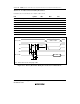
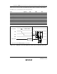
Data
CE
FA17 to FA0
FO7 to FO0
FO6
FO7
OE
WE
t
nxtc
t
wsts
t
nxtc
t
ces
t
ds
t
dh
t
wep
t
as
t
ah
t
ceh
Address
stable
Programming wait
Data transfer
1 byte to 128 bytes
H'40
Data
FO0 to FO5 = 0
t
f
t
r
t
spa
t
write
(1 to 3000 ms)
Programming normal
end identification signal
Programming operation
end identification signal
Figure 23.20 Auto-Program Mode Timing Waveforms
Notes on Use of Auto-Program Mode
• In auto-program mode, 128 bytes are programmed simultaneously. This should be carried out
by executing 128 consecutive byte transfers.
• A 128-byte data transfer is necessary even when programming fewer than 128 bytes. In this
case, H'FF data must be written to the extra addresses.
• The lower 8 bits of the transfer address must be H'00 or H'80. If a value other than an effective
address is input, processing will switch to a memory write operation but a write error will be
flagged.
• Memory address transfer is performed in the second cycle (figure 23.20). Do not perform
transfer after the second cycle.
• Do not perform a command write during a programming operation.
• Perform one auto-programming operation for a 128-byte block for each address.
Characteristics are not guaranteed for two or more programming operations.
• Confirm normal end of auto-programming by checking FO6. Alternatively, status read mode
can also be used for this purpose (FO7 status polling uses the auto-program operation end
identification pin).
• The status polling FO6 and FO7 pin information is retained until the next command write.
Until the next command write is performed, reading is possible by enabling CE and OE.