
Datasheet


Section 24 Clock Pulse Generator
Rev. 4.00 Sep 27, 2006 page 739 of 1130
REJ09B0327-0400
24.4 Duty Adjustment Circuit
When the oscillator frequency is 5 MHz or higher, the duty adjustment circuit adjusts the duty
cycle of the clock signal from the oscillator to generate the system clock (φ).
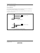
24.5 Medium-Speed Clock Divider
The medium-speed clock divider divides the system clock to generate φ/2, φ/4, φ/8, φ/16, and φ/32
clocks.
24.6 Bus Master Clock Selection Circuit
The bus master clock selection circuit selects the system clock (φ) or one of the medium-speed
clocks (φ/2, φ/4, φ/8, φ/16, or φ/32) to be supplied to the bus master, according to the settings of
bits SCK2 to SCK0 in SBYCR.
24.7 Subclock Input Circuit
The subclock input circuit controls the subclock input from the EXCL pin.
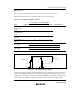
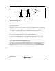
Inputting the Subclock
When a subclock is used, a 32.768 kHz external clock should be input from the EXCL pin. In this
case, clear bit P96DDR to 0 in P9DDR and set bit EXCLE to 1 in LPWRCR.
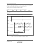
The subclock input conditions are shown in table 24.6 and figure 24.8.
Table 24.6 Subclock Input Conditions
V
CC
= 2.7 to 5.5 V
Item Symbol Min Typ Max Unit Test Conditions
Subclock input low pulse
width
t
EXCLL
— 15.26 — µs Figure 24.8
Subclock input high pulse
width
t
EXCLH
— 15.26 — µs
Subclock input rise time t
EXCLr
—— 10 ns
Subclock input fall time t
EXCLf
—— 10 ns