
Datasheet


Section 5 Interrupt Controller
Rev.7.00 Dec. 24, 2008 Page 107 of 698
REJ09B0074-0700
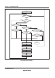
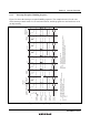
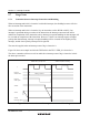
5.6.3 Interrupt Exception Handling Sequence
Figure 5.6 shows the interrupt exception handling sequence. The example shown is for the case
where interrupt control mode 0 is set in advanced mode, and the program area and stack area are in
on-chip memory.
(14)(12)(10)(6)(4)(2)
(1) (5) (7) (9) (11) (13)
Interrupt service
routine instruction
prefetch
Internal
operation
Vector fetchstack
Instruction
prefetch
Internal
operation
Interrupt
acceptance
Interrupt level determination
Wait for end of instruction
Interrupt
request signal
Internal
address bus
Internal
read signal
Internal
write signal
Internal
data bus
φ
(3)
(1)
(2) (4)
(3)
(5)
(7)
Instruction prefetch address (Not executed.
This is the contents of the saved PC, the return address)
Instruction code (Not executed)
Instruction prefetch address (Not executed)
SP-2
SP-4
Saved PC and saved CCR
Vector address
Interrupt handling routine start address (Vector address contents)
Interrupt handling routine start address ((13) = (10) (12))
First instruction of interrupt handling routine
(6) (8)
(9) (11)
(10) (12)
(13)
(14)
(8)
Figure 5.6 Interrupt Exception Handling