
Datasheet


Section 6 Bus Controller
Rev.7.00 Dec. 24, 2008 Page 119 of 698
REJ09B0074-0700
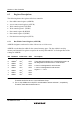
6.3.2 Access State Control Register (ASTCR)
ASTCR designates each area as either a 2-state access space or a 3-state access space.
ASTCR sets the number of access states for the external memory space. The number of access
states for on-chip memory and internal I/O registers except for the on-chip USB is fixed regardless
of the settings in ASTCR.
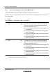
Bit Bit Name Initial Value R/W Description
7
6
5
4
3
2
1
0
AST7*
AST6*
AST5
AST4
AST3
AST2
AST1
AST0
1
1
1
1
1
1
1
1
R/W
R/W
R/W
R/W
R/W
R/W
R/W
R/W
Area 7 to 0 Access State Control:
These bits select whether the corresponding area is to
be designated as a 2-state access space or a 3-state
access space. Wait state insertion is enabled or disabled
at the same time.
0: Area n is designated for 2-state access
Wait state insertion in area n external space is
disabled
1: Area n is designated for 3-state access
Wait state insertion in area n external space is
enabled
Legend: n = 7 to 0
Note: * The on-chip USB and on-chip RTC are allocated to area 6 and area 7, respectively.
Therefore, these bits should be set to 1.