
Datasheet


Section 6 Bus Controller
Rev.7.00 Dec. 24, 2008 Page 127 of 698
REJ09B0074-0700
6.4 Bus Control
6.4.1 Area Divisions
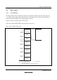
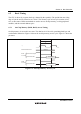
In advanced mode, the bus controller partitions the 16 Mbytes address space into eight areas, 0 to
7, in 2-Mbyte units, and performs bus control for external space in area units. In normal mode*, it
controls a 64-kbyte address space comprising part of area 0.
Figure 6.2 shows an outline of the memory map.
Chip select signals (CS0 to CS5) can be output for areas 0 to 5.
Note: * Not available in this LSI.
Area 0
(2 Mbytes)
H'000000
H'FFFFFF
(1) (2)
H'0000
H'1FFFFF
H'200000
Area 1
(2 Mbytes)
H'3FFFFF
H'400000
Area 2
(2 Mbytes)
H'5FFFFF
H'600000
Area 3
(2 Mbytes)
H'7FFFFF
H'800000
Area 4
(2 Mbytes)
H'9FFFFF
H'A00000
Area 5
(2 Mbytes)
H'BFFFFF
H'C00000
Area 6
(2 Mbytes)
H'DFFFFF
H'E00000
Area 7
(2 Mbytes)
H'FFFF
Advanced mode
Normal mode
*
1
Notes: 1. Not available in this LSI.
2. This area is allocated to the on-chip USB in this LSI.
*
2
Figure 6.2 Overview of Area Divisions