
Datasheet

Section 7 DMA Controller (DMAC)
Rev.7.00 Dec. 24, 2008 Page 193 of 698
REJ09B0074-0700
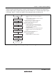
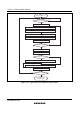
Transfer requests (activation sources) consist of A/D conversion end interrupt, SCI transmission
complete and reception complete interrupts, and TPU channel 0 to 2 compare match/input capture
A interrupts. For details, see section 7.3.4, DMA Control Register (DMACR). Figure 7.13 shows
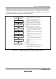
an example of the setting procedure for block transfer mode.
Block transfer
mode setting
Set DMABCRH
Set transfer source
and transfer destination
addresses
Set number of transfers
Set DMACR
Read DMABCRL
Set DMABCRL
Block transfer mode
[1]
[2]
[3]
[4]
[5]
[6]
[1] Set each bit in DMABCRH.
· Set the FAE bit to 1 to select full address
mode.
· Specify enabling or disabling of internal
interrupt clearing with the DTA bit.
[2] Set the transfer source address in MARA, and
the transfer destination address in MARB.
[3] Set the transfer source address in ETCRAH
and ETCRAL. Set the number of transfers in
ETCRB.
[4] Set each bit in DMACRA and DMACRB.
· Set the transfer data size with the DTSZ bit.
· Specify whether MARA is to be incremented,
decremented, or fixed, with the SAID and
SAIDE bits.
· Set the BLKE bit to 1 to select block transfer
mode.
· Specify whether the transfer source or the
transfer destination is a block area with the
BLKDIR bit.
· Specify whether MARB is to be incremented,
decremented, or fixed, with the DAID and
DAIDE bits.
· Select the activation source with bits DTF3
to DTF0.
[5] Read the DTE = 0 and DTME = 0 in
DMABCRL.
[6] Set each bit in DMABCRL.
· Specify enabling or desabling of transfer end
interrupts to the CPU with the DTIE bit.
· Set both the DTME bit and the DTE bit to 1
to enable transfer.
Figure 7.13 Example of Block Transfer Mode Setting Procedure