
Datasheet


Section 9 16-Bit Timer Pulse Unit (TPU)
Rev.7.00 Dec. 24, 2008 Page 294 of 698
REJ09B0074-0700
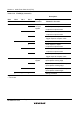
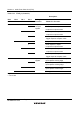
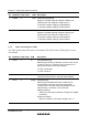
Bit Bit Name Initial value R/W Description
1 TGIEB 0 R/W TGR Interrupt Enable B
Enables or disables interrupt requests (TGIB) by the
TGFB bit when the TGFB bit in TSR is set to 1.
0: Interrupt requests (TGIB) by TGFB disabled
1: Interrupt requests (TGIB) by TGFB enabled
0 TGIEA 0 R/W TGR Interrupt Enable A
Enables or disables interrupt requests (TGIA) by the
TGFA bit when the TGFA bit in TSR is set to 1.
0: Interrupt requests (TGIA) by TGFA disabled
1: Interrupt requests (TGIA) by TGFA enabled
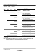
9.3.5 Timer Status Register (TSR)
The TSR registers indicate the status of each channel. The TPU has three TSR registers, one for
each channel.
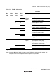
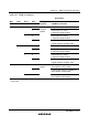
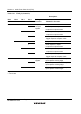
Bit Bit Name Initial value R/W Description
7 TCFD 1 R Count Direction Flag
Status flag that shows the direction in which TCNT counts
in channel 1 and 2. In channel 0, bit 7 is reserved. It is
always read as 0 and cannot be modified.
0: TCNT counts down
1: TCNT counts up
6 – 1 – Reserved
This bit is always read as 1 and cannot be modified.
5 TCFU 0 R/(W)* Underflow Flag
Status flag that indicates that TCNT underflow has
occurred when channels 1 and 2 are set to phase
counting mode. The write value should always be 0 to
clear this flag. In channel 0, bit 5 is reserved.
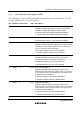
[Setting condition]
When the TCNT value underflows (change from H'0000
to H'FFFF)
[Clearing condition]
When 0 is written to TCFU after reading TCFU = 1