
Datasheet


Section 12 Serial Communication Interface
Rev.7.00 Dec. 24, 2008 Page 395 of 698
REJ09B0074-0700
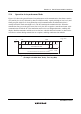
12.3.11 Bit Rate Register (BRR)
BRR is an 8-bit register that adjusts the bit rate. As the SCI performs baud rate generator control
independently for each channel, different bit rates can be set for each channel. Table 12.2 shows
the relationships between the N setting in BRR and bit rate B for normal asynchronous mode,
clocked synchronous mode, and Smart Card interface mode. The initial value of BRR is H'FF, and
it can be read from or written to by the CPU at all times.
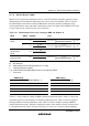
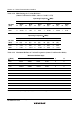
Table 12.2 Relationships between the N Setting in BRR and Bit Rate B
Mode ABCS Bit Rate Error
0
B =
64 × 2
2n-1
× (N + 1)
φ × 10
6
Error (%) = – 1 × 100
B × 64 × 2
2n-1
× (N + 1)
φ × 10
6
Asynchronous
mode
1
B =
32 × 2
2n-1
× (N + 1)
φ × 10
6
Error (%) = – 1 × 100
B × 32 × 2
2n-1
× (N + 1)
φ × 10
6
Clocked
synchronous
mode
×
B =
8 × 2
2n-1
× (N + 1)
φ × 10
6
⎯
Smart Card
interface mode
×
B =
S × 2
2n+1
× (N + 1)
φ × 10
6
Error (%) = – 1 × 100
B × S × 2
2n+1
× (N + 1)
φ × 10
6
Legend:
B: Bit rate (bps)
N: BRR setting for baud rate generator (0 ≤ N ≤ 255)
φ: Operating frequency (MHz)
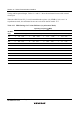
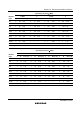
n, S: Determined by the SMR settings shown in the following tables.
×: Don’t care
SMR Setting SMR Setting
CKS1 CKS0 Clock Source n BCP1 BCP0 S
0 0 φ 0 0 0 32
0 1 φ/4 1 0 1 64
1 0 φ/16 2 1 0 372
1 1 φ/64 3 1 1 256
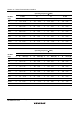
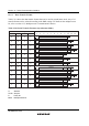
Table 12.3 shows sample N settings in BRR in normal asynchronous mode. Table 12.4 shows the
maximum bit rate for each frequency in normal asynchronous mode. Table 12.6 shows sample N
settings in BRR in clocked synchronous mode. Table 12.8 shows sample N settings in BRR in
Smart Card interface mode. In Smart Card interface mode, S (the number of basic clock periods in
a 1-bit transfer interval) can be selected. For details, see section 12.7.5, Receive Data Sampling