
Datasheet

Section 12 Serial Communication Interface
Rev.7.00 Dec. 24, 2008 Page 408 of 698
REJ09B0074-0700
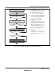
12.4.5 Data Transmission (Asynchronous Mode)
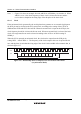
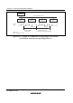
Figure 12.9 shows an example of operation for transmission in asynchronous mode. In
transmission, the SCI operates as described below.
1. The SCI monitors the TDRE flag in SSR. If the flag is cleared to 0, the SCI recognizes that
data has been written to TDR, and transfers the data from TDR to TSR.
2. After transferring data from TDR to TSR, the SCI sets the TDRE flag to 1 and starts
transmission. If the TIE bit is set to 1 at this time, a transmit data empty interrupt request (TXI)
is generated. Continuous transmission is possible because the TXI interrupt routine writes next
transmit data to TDR before transmission of the current transmit data has been completed.
3. Data is sent from the TxD pin in the following order: start bit, transmit data, parity bit or
multiprocessor bit (may be omitted depending on the format), and stop bit.
4. The SCI checks the TDRE flag at the timing for sending the stop bit.
5. If the TDRE flag is 0, the data is transferred from TDR to TSR, the stop bit is sent, and then
serial transmission of the next frame is started.
6. If the TDRE flag is 1, the TEND flag in SSR is set to 1, the stop bit is sent, and then the "mark
state" is entered, in which 1 is output. If the TEIE bit in SCR is set to 1 at this time, a TEI
interrupt request is generated.
TDRE
TEND
0
1 frame
D0 D1 D7 0/1 1 0 D0 D1 D7 0/1 1
1 1
DataStart
bit
Parity
bit
Stop
bit
Start
bit
Data Parity
bit
Stop
bit
TXI interrupt
request generated
Data written to TDR and
TDRE flag cleared to 0 in
TXI interrupt service routine
TEI interrupt
request generated
Idle state
(mark state)
TXI interrupt
request generated
Figure 12.9 Example of Operation in Transmission in Asynchronous Mode
(Example with 8-Bit Data, Parity, One Stop Bit)
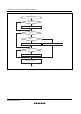
Figure 12.10 shows a sample flowchart for transmission in asynchronous mode.