
Datasheet


Section 12 Serial Communication Interface
Rev.7.00 Dec. 24, 2008 Page 438 of 698
REJ09B0074-0700
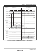
12.8 SCI Select Function (Clocked Synchronous Mode)
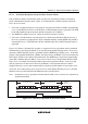
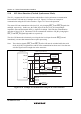
The SCI_0 supports the SCI select function which allows clock synchronous communication
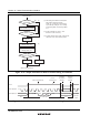
between master LSI and one of multiple slave LSI. Figure 12.36 shows an example of
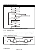
communication using the SCI select function. Figure 12.37 shows the operation.
The master LSI can communicate with slave LSI_A by bringing SEL_A and SEL_B signals low
and high, respectively. In this case, the TxD0_B pin of the slave LSI_B is brought high-
impedance state and the internal SCK0_A signal is fixed high. This halts the communication
operation of slave LSI_B. The master LSI can communicate with slave LSI_B by bringing the
SEL_A and SEL_B signals high and low, respectively.
The slave LSI detects the selection by receiving the low level input from the IRQ7 pin and
immediately executes data transmission/reception processing.
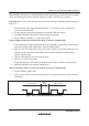
Note: The selection signals (SEL_A and SEL_B) of the LSI must be switched while the serial
clock (M_SCK) is high after the end bit of the transmit data has been send. Note that one
selection signal can be brought low at the same time.
Interrupt
controller
TSR0_ARSR0_A
Transmission/
reception
control
Slave LSI_A (This LSI)Master LSI
SCK0_A
SCK0_B
C/A = CKE1 = SSE = 1
Slave LSI_B (This LSI)
SEL_A
IRQ7_A
IRQ7_BSEL_B
M_TxD
RxD0_A
TxD0_A
RxD0_B
TxD0_B
SCK0
SCK0
M_RxD
M_SCK
Figure 12.36 Example of Communication Using the SCI Select Function