
Datasheet

Section 14 Universal Serial Bus (USB)
Rev.7.00 Dec. 24, 2008 Page 501 of 698
REJ09B0074-0700
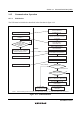
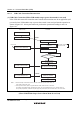
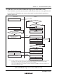
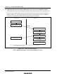
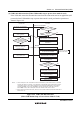
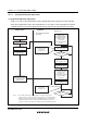
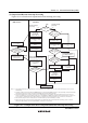
(4) USB Cable Disconnection (When USB module stop or power-down mode is used)
If the USB cable enters the disconnection state from the connection state in an application (self
powered) where USB module stop or power-down mode is used, perform the operation as
shown in figure 14.6.
Disconnect the USB cable
USB function
Firmware
No
Yes
Enable D+ pull-up
by port 36 (P36)
Enter power-down mode
(only if necessary)
Wait for USB
cable connection
Yes
Yes
Yes
No
No
No
Stop USB module
Write MSTPB0 in MSTPCRB to 1
Reset UDC core
Write UDCRST in UCTRL to 1
Reset UDC core
System needs to
enter power-down
mode?
*
1
*
2
*
2
1.
2.
EXIRQx
External interrupt IRQx*
1
Notes:
VBUS interrupts in the USB module cannot be detected in power-down mode or in the USB
module stop state. Accordingly, in an application (self powered) where power-down mode or
USB module stop is used , VBUS interrupts of the USB must bedetected via the external
interrupt pin IRQx. In this case, the IRQx pin must be specified as both edge sensitive.
When IRQx is used, VBUS interrupts in the USB module need not to be used.
Before entering power-down mode, make sure to set USB module stop2 (the MSTPB0 bit of
MSTPCRB = 1).
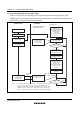
Check the USB cable
disconnection state
Start USB operating
clock oscillation
USB operating
clock stabilization time
has passed?
USB operating clock
stabilization detection
interrupt occurs.
Powe-down mode ?
USB module
stopped?
Cancel USB module stop 2
Clear MSTPB0 in MSTPCRB to 0
Wait for USB operating clock
stabilization
Check connections by using
the port function of IRQx
Clear CK48READY in UIFR3 to 0
Figure 14.6 USB Cable Disconnection
(When USB Module Stop or Power-Down Mode Is Used)