
Datasheet

Section 14 Universal Serial Bus (USB)
Rev.7.00 Dec. 24, 2008 Page 504 of 698
REJ09B0074-0700
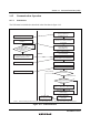
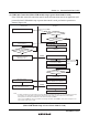
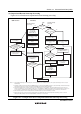
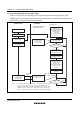
(3) Suspend and Remote-Wakeup Operations
Figures 14.9 and 14.10 are flowcharts of the suspend and remote-wakeup operations. If the
USB bus enters a non-suspend state from the suspend state due to a remote-wakeup signal from
this function, perform the operations shown below.
USB function Firmware
USB cable connected
A bus idle of 3 ms or
more occurs
A suspend/resume
interrupt occurs
Suspend state
Output resume signal
to USB bus
A suspend/resume
interrupt occurs
Enable SPRSi and
IRQ6 interrupts
(Set SPRSiE in UIER3 to 1)
(Set IRQ6E in IER to 1)
Initialize standby
enable flag
(Clear standby enable
flag to 0)
Run user program
In one of the power-down
modes
Mask all interrupts
(Manipulate bit I using
LDC instruction, etc.)
Enable IRQ6 interrupt
(Set IRQ6E in IER to 1)
Unmask all interrupts
(Clear bit I using LDC
instruction, etc.)
Transition to one
of the power-down modes
(Execute SLEEP
instruction)
Suspend interrupt
processing
(see figure 14.8)
IRQ6
NMI or IRQx
IRQ6
Suspend/remote-wakeup
interrupt processing
Main process
No
No
Yes
Yes
Standby enable
flag = 0?
Remote-wakeup
interrupt processing
(see figure 14.10)
*1
*1
*1
*2
*2
*2
Standby enable
flag = 1?
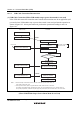
Notes: 1. The standby enable flag is a software flag for controlling transition to the standby
state (one of the power-down modes). There is no such hardware flag.
2. Interrupts should be masked from when the IRQ6 interrupt is received until the
SLEEP instruction is executed. Finally, unmask the interrupts using the LDC
instruction or the like and execute the SLEEP instruction immediately afterward.
Remote-
wakeup
Figure 14.9 Example Flowchart of Suspend and Remote-Wakeup Operations