
Datasheet


Section 17 Flash Memory (F-ZTAT Version)
Rev.7.00 Dec. 24, 2008 Page 562 of 698
REJ09B0074-0700
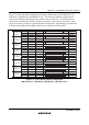
17.5.1 Flash Memory Control Register 1 (FLMCR1)
FLMCR1 is a register that makes the flash memory transit to program mode, program-verify
mode, erase mode, or erase-verify mode. For details on register setting, refer to section 17.8, Flash
Memory Programming/Erasing.
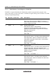
Bit Bit Name Initial Value R/W Description
7 FWE —* R Flash Write Enable
Reflects the input level at the FWE pin. It is set to 1
when a low level is input to the FWE pin, and cleared to
0 when a high level is input.
6 SWE1 0 R/W Software Write Enable
When this bit is set to 1, flash memory
programming/erasing is enabled. When this bit is
cleared to 0, other FLMCR1 register bits and all EBR1,
EBR2 bits cannot be set.
[Setting condition]
When FWE = 1
5 ESU1 0 R/W Erase Setup
When this bit is set to 1, the flash memory transits to the
erase setup state. When it is cleared to 0, the erase
setup state is cancelled. Set this bit to 1 before setting
the E1 bit in FLMCR1.
[Setting condition]
When FWE = 1 and SWE1 = 1
4 PSU1 0 R/W Program Setup
When this bit is set to 1, the flash memory transits to the
program setup state. When it is cleared to 0, the
program setup state is cancelled. Set this bit to 1 before
setting the P1 bit in FLMCR1.
[Setting condition]
When FWE = 1 and SWE1 = 1
3 EV1 0 R/W Erase-Verify
When this bit is set to 1, the flash memory transits to
erase-verify mode. When it is cleared to 0, erase-verify
mode is cancelled.
[Setting condition]
When FWE = 1 and SWE1 = 1