
Datasheet


Section 17 Flash Memory (F-ZTAT Version)
Rev.7.00 Dec. 24, 2008 Page 569 of 698
REJ09B0074-0700
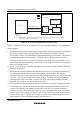
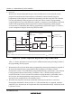
5. In boot mode, a part of the on-chip RAM area (four kbytes) is used by the boot program. The
area to which the programming control program is transferred from the host is 8 kbytes
(H'FFC000 to H'FFDFFF) in the HD64F2218 and HD64F2212 and 4 kbytes (H'FFD000 to
H'FFDFFF) in the HD64F2211. The boot program area cannot be used until the execution
state in boot mode switches to the programming control program.
6. Before branching to the programming control program, the chip terminates transfer operations
by the SCI_2 (by clearing the RE and TE bits in SCR to 0), but the adjusted bit rate value
remains set in BRR. Therefore, the programming control program can still use it for transfer of
write data or verify data with the host. The TxD pin is high. The contents of the CPU general
registers are undefined immediately after branching to the programming control program.
These registers must be initialized at the beginning of the programming control program, since
the stack pointer (SP), in particular, is used implicitly in subroutine calls, etc.
7. Boot mode can be cleared by a reset. End the reset* after driving the reset pin low, waiting at
least 20 states, and then setting the FWE pin and the mode (MD) pins. Boot mode is also
cleared when a WDT overflow occurs.
8. Do not change the MD pin input levels in boot mode. If the mode pin input levels are changed
(for example, from low to high) during a reset, the state of ports with multiplexed address
functions and bus control output pins (AS, RD, WR) will change according to the change in
the microcomputer’s operating mode . Therefore, care must be taken to make pin settings to
prevent these pins from becoming output signal pins during a reset, or to prevent collision with
signals outside the microcomputer.
9. All interrupts are disabled during programming or erasing of the flash memory.
Note:* Mode pin and FWE pin input must satisfy the mode programming setup time (t
MDS
= 200
ns) with respect to the reset release timing.