
Datasheet

Section 17 Flash Memory (F-ZTAT Version)
Rev.7.00 Dec. 24, 2008 Page 586 of 698
REJ09B0074-0700
17.12 Power-Down States for Flash Memory
In user mode, the flash memory will operate in either of the following states:
• Normal operating mode
The flash memory can be read and written to.
• Standby mode
All flash memory circuits are halted.
• Power-down state
The flash memory can be read when part of the power supply circuit is halted and the LSI
operates by subclocks.
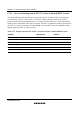
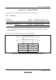
Table 17.8 shows the correspondence between the operating modes of this LSI and the flash
memory. When the flash memory returns to normal operation from a power-down state, a power
supply circuit stabilization period is needed. When the flash memory returns to its normal
operating state from watch mode or standby mode, bits STS2 to STS0 in SBYCR must be set to
provide a wait time of at least 100 μs; when returns from flash memory module stop mode, the
software wait state should be set.
Table 17.8 Flash Memory Operating States
LSI Operating State Flash Memory Operating State
Active mode Normal operating mode
Sleep mode
Watch mode
Standby mode
Flash memory module stop
mode
Standby mode
(Before entering to the normal operation mode, wait time of at least
100 µs is required.)
Subactive mode
Subsleep mode
Power-down mode (read only)