
Emulation Pod User's Manual

( 13 / 72 )
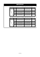
Notes on HOLD* Input:
• Be sure to input "Low" to the HOLD* pin of the target system during the user program executing
(while the RUN status LED on the PC4701's front panel is lit). Inputting "Low" to the HOLD* pin
when stopping the user program or when run-time debugging may cause a malfunction of the
emulator.
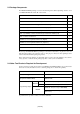
• When inputting "Low" to the HOLD* pin to run into the HOLD state, P00 to P52 will be in the HOLD
state delaying by 2.5 cycles than the actual MCU (see Table 5.5, Figure 5.5).
Note on Software Reset:
• Do not use a software reset.
Note on Protect Resister (PRC2):
• Make note of the fact that the protect is not canceled when the protect register (PRC2), which
enables writing in the port P9 direction register, is changed with the below procedure.
(1) Step execution of the "instruction for setting ("1") PRC2".
(2) Setting the break point from the "instruction for setting ("1") PRC2" to the "setting the register
for the protect".
(3) "Setting ("1") PRC2" from the dump window, script window or others.
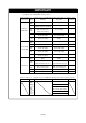
IMPORTANT
Note on NMI* Input:
• NMI* input from the target system is accepted only while a user program is being executed (only
while the RUN status LED on the PC4701's front panel is lit).
Notes on Address Match Interrupt:
• Do not set software breaks at the same addresses as address-match interrupts as the program may
run out of control.
• Do not set a hardware break within 4 instructions before an address at which an address-match
interrupt occurs. If you do set a hardware break in this range, the program will run out of control.
•When an address at which an address-match interrupt occurs is executed in one-step mode, the
program stops after executing the first instruction after returning from the address-match interrupt
processing.
Note on Setting BCLK Output Disable Bit (PM07):
•Do not set the 7th bit (PM07: BCLK output disable bit) of the processor mode register 0 (address
000416) to "1". Otherwise, this emulation pod does not work properly.