
Emulation Pod User's Manual

( 34 / 72 )
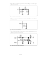
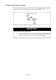
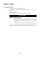
Figure 3.10 Signal circuits of HLF pin
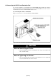
(3) Figure 3.11 shows the number of part which is connected to VHOLD pin, the constant of part and
the connection circuit.
(2) Figure 3.10 shows the numbers of parts which are connected to HLF pin, the constants of parts
and the connection circuits.
Figure 3.11 Signal circuit of VHOLD pin
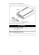
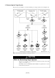
(4) Figure 3.12 shows the numbers of parts which are connected to OSC1 and OSC2 pins, the
constants of parts and the connection circuits.
Figure 3.12 Signal circuits of OSC1 and OSC2 pins