M37760T-RPD-E Emulation Pod for 7760 Group 7760/7762/776A MCUs (for PC4701 Emulator System) User's Manual Rev. 2.
* IC61-1004-051 is a product of Yamaichi Electronics Co., Ltd. Keep safety first in your circuit designs! • Renesas Technology Corporation and Renesas Solutions Corporation put the maximum effort into making semiconductor products better and more reliable, but there is always the possibility that trouble may occur with them. Trouble with semiconductors may lead to personal injury, fire or property damage.
Preface The M37760T-RPD-E is an emulation pod for the 7700 Family 7770 Series 7760 Group 7760/7762/ 776A of Renesas 16-bit MCUs. It is used with a PC4701 emulator. This user's manual mainly describes specifications of the M37760T-RPD-E emulation pod and how to setup it. For details on the following products, which are used with the M37760T-RPD-E, refer to each product's user's manual.
Terminology Some specific words used in this user's manual are defined as follows: Emulator system This means an emulator system built around the PC4701 emulator. The PC4701 emulator system is configured with an emulator main unit, emulation pod, host machine and emulator debugger. Emulator main unit (Hereafter PC4701) This means the emulator main units for 8 and 16-bit MCUs. For details on PC4701, visit Renesas Tool Homepage at http://www.renesas.
Contents Chapter 1. Precautions for Safety ........................................................................................... 7 1.1 Safety Symbols and Meanings .............................................................................. 8 Chapter 2. Preparation .......................................................................................................... 15 2.1 Package Components .......................................................................................... 16 2.
4.5 Self-check ............................................................................................................ 40 (1) Self-check Procedure ............................................................................... 40 (2) If an Error is Detected in the Self-check .................................................. 40 Chapter 5. Specifications ...................................................................................................... 43 5.1 Specifications ..........................
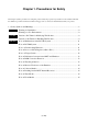
Chapter 1. Precautions for Safety This chapter describes precautions for using this product safely and properly. For precautions for the emulator main unit, the emulation pod main unit and the emulator debugger, refer to each user's manual included with your product. 1.1 Safety Symbols and Meanings ..................................................................................................... 8 WARNING Warning for Installation ........................................................................
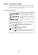
Chapter 1. Precautions for Safety In both the user's manual and on the product itself, several icons are used to insure proper handling of this product and also to prevent injuries to you or other persons, or damage to your properties. This chapter describes the precautions which should be taken in order to use this product safely and properly. Be sure to read this chapter before using this product. 1.
WARNING Warning for Installation: • Do not set this product in water or areas of high humidity. Spilling water or some other liquid into the main unit can cause an unrepairable damage. Warnings for Use Environment: • The emulation pod is air-cooled with the ventilation slot. Therefore, do not block the ventilation slot. When heated to high temperatures, the emulation pod may not work properly. • This equipment is to be used in an environment with a maximum ambient temperature of 35°C.
(1) Set the target system on a platform to relax bends and relieve stress in the board. (2) The boundary between the firm and flexible parts of the flexible board does not ready bend. Do not bend it excessively. When bending the flexible board, keep R to 30 mm or more as shown at left. Figure 1.
IMPORTANT Note on Malfunctions in the PC4701 System: • If the emulator malfunctions because of interference such as external noise, do the following to remedy the trouble. (1) Press the RESET button on the emulator front panel. (2) If normal operation is not restored after step (1), shut OFF power to the emulator once and then reactivate it. Note for PC4700 System: • PC4700H products whose serial number ends with a number or D, DE, G cannot be used with the M37760T-RPD-E.
IMPORTANT Note on Processor Mode Register (address D816): • When using this product, the following precautions must be observed with the processor mode register 0 in addition to those for the actual MCU. (1) Software reset bit (bit 3) If "1" is set for the software reset bit when the user program is not running, the MCU will be reset while debug commands are being executed, thus commands will not end as they normally do.
IMPORTANT Note on Differences between Actual MCU and Emulator: • Operations of the emulator differ from those of mask MCUs as listed below. (1) Reset condition (2) Power voltage (3) Initial values of internal resource data at power-on (4) Internal memory (ROM and RAM) capacities, etc.
IMPORTANT Note on Monitor Work Area of the Emulator: • Please note that this emulator uses the following areas of the MCU access space as monitor work areas. For details, refer to "5.2 Memory Mapping" (page 45). (1) User stack: Part of the user stack area from the address indicated by the stack pointer toward the lower address direction. (Normally 9 bytes, Max. 14 bytes) (2) Monitor work area: Part of an area in bank 00 (any 6 bytes) Part of the vector area in bank 00 (Min. 2 bytes, Max.
Chapter 2. Preparation This chapter describes the package components, the system configuration and the preparation for using this product for the first time. 2.1 Package Components.................................................................................................................. 16 2.2 Other Tool Products Required for Development........................................................................ 16 2.3 Name of Each Part ..................................................................
Chapter 2. Preparation 2.1 Package Components This product consists of the following items. When unpacking, check to see if your product package contains all of these items.
2.3 Name of Each Part (1) System Configuration Figure 2.1 System configuration (1) to (4) in Figure 2.1 are included in this product package. (1) Emulation pod (M37760T-RPD-E) This emulation pod contains an evaluation MCU, emulation memory and circuit to feature the debugging functions. (2) Flexible cable (FLX120-RPD) This 120-pin flexible cable connects the PC4701 emulator and the emulation pod. (3) Flexible cable (FLX100) This 100-pin flexible cable connects the emulation pod and the target system.
(2) Inside of the Emulation Pod (1) Base board RCA connectors Socket for evaluation MCU (2) Memory board (3) Oscillation circuit board (for XIN) RCA connectors (4) Oscillation circuit board (for OSCIN3) Figure 2.2 Internal view of the emulation pod (1) Base board Base board for the 7760 Group 7760/7762/776A MCUs which controls the interface of the PC4701 and evaluation MCU. (2) Memory board Board on which the 1MB emulation memory is mounted.
2.4 When Using the Emulator for the First Time If you have purchased this emulation pod newly, it is necessary to download the firmware. The download procedure is given in Figure 2.3. Before attempting to download the firmware, check the emulator debugger is installed and the emulator is connected to the host machine. For more information, see each user's manual of the emulator debugger and the PC4701. Connect the PC4701 and this product. See "3.4 Connecting the PC4701" (page 29).
MEMO ( 20 / 64 )
Chapter 3. Setting Up This chapter describes switch settings required for using this product and how to connect this product to the PC4701 and the target system. 3.1 Removing the Upper Cover ........................................................................................................ 22 3.2 Switch Settings ........................................................................................................................... 23 3.3 Selecting Clock Supply .....................................
Chapter 3. Setting Up With this product, it is necessary to set the following according to your target system. Set the following after removing the upper cover. • Setting XIN/XOUT pins • Setting XCIN/XCOUT pins • Changing the input frequency • Setting the MCU peripheral functions 3.1 Removing the Upper Cover The procedure of removing the upper cover is shown below. (1) Remove the eight screws of this product and lift off the upper cover (see Figure 3.1). (2) Set the jumper switches.
3.2 Switch Settings Figure 3.2 shows the positions of the switches and Table 3.1 shows each switch setting. Figure 3.2 Positions of the switches and their factory-settings * For the circuit configuration of these switches, refer to "5.3 Connection Diagram" (page 46).
Table 3.1 Switch settings of the M37760T-RPD-E Switch setting Description P31 side XCIN side When using P31/XCIN pin as a When using P31/XCIN pin as a port, set to P31 side. sub-clock, set to XCIN side. SW1 XCIN P31 (Factory-setting) USENSE USENSE side Be sure to fix to this side. NC side Do not use this side. JP23 NC (Factory-setting) XOUT XOUT side NC side Connects the XOUT pin to the Does not connect the XOUT pin target system. to the target system. XOUT pin is open.
3.3 Selecting Clock Supply There are two ways to supply a clock to the MCU, using the oscillator circuit of the emulation pod or using the oscillator circuit on the target system. Table 3.2 shows the factory-settings of each clock supply. Table 3.2 Clock supply to the MCU Clock Description Display of emulator debugger Factory-setting Internal oscillator circuit of emulation pod (OSC-3: 16 MHz) Internal Yes Target system External - Internal oscillator circuit of emulation pod (32.
(1) Using the Oscillator Circuit on the Target System When turning on the power supply, the internal clock of the emulation pod is selected to supply the clock to the MCU. To use the external clock on the target system, change the clock by the CLK command of the emulator debugger. (For details, refer to the user's manual of the emulator debugger.
(2) Changing the Internal Oscillator Circuit of the Emulation Pod An oscillator circuit board for 16 MHz (for XIN) and 14.318 MHz (for OSCIN3) are mounted on the emulation pod. To use the emulation pod at a frequency other than 16 MHz or 14.318 MHz, build the desired oscillator circuit on the included OSC-2 oscillator circuit board (bare board) and replace the board installed in the emulation pod when shipped from the factory. Figure 3.
(3) Replacing the Oscillator Circuit Boards Figure 3.7 shows how to replace the oscillator circuit boards. For the position of the oscillator circuit board, see "Figure 2.2 Internal view of the emulation pod" (page 18). (1) Unscrew the screw securing the oscillator circuit board. (2) Lift off the oscillator circuit board. (3) Attach the J1 connector of another oscillator circuit board for replacement to the J1 (OSCIN3) or J2 (XIN) connector of the base board.
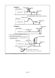
3.4 Connecting the PC4701 To connect the emulation pod to the PC4701, use the FLX120-RPD 120-pin flexible cable included in this product package. Connect the PC4701 side connector of the FLX120-RPD to the cable connector of the PC4701, then secure with screws. (1) Connecting the Cable to the PC4701 Figure 3.8 shows how to connect the PC4701 and FLX120-RPD. Figure 3.
(2) Connecting the Cable to the Emulation Pod Figure 3.9 shows how to connect the FLX120-RPD and the emulation pod. Figure 3.9 Connecting emulation pod and FLX120-RPD CAUTION Note on Connecting the Cable: • Always shut OFF power before connecting the cable. The power ON state could destroy internal circuits. Note on Securing the Screws: • After connecting the emulator main unit to the cable, be sure to secure the screws.
3.5 Connecting the Target System There are four ways available to connect the emulation pod to target system as shown in Figure 3.10. Figure 3.10 Connecting emulation pod and target system *1 These three items are available in one package. *2 M3T-FLX-100LCC is included in this emulation pod package. *3 To purchase IC socket IC61-1004-051 (manual soldering type), contact your local distributor or Yamaichi Electronics Co., Ltd.
MEMO ( 32 / 64 )
Chapter 4. Usage This chapter describes from turning on the power of this product to starting up the emulator debugger. 4.1 Turning On the Power Supply .................................................................................................... 34 (1) Checking the Connection of the System ............................................................................... 34 (2) Turning On the Power Supply ..............................................................................................
Chapter 4. Usage 4.1 Turning On the Power Supply (1) Checking the Connection of the System Before turning the power ON, check the connection of the PC4701, emulation pod, converter board and target system. (2) Turning On the Power Supply Power ON/OFF the target system and the PC4701 as simultaneously as possible. CAUTION Notes on Power Supply: • The emulator's VCC pin is connected to the target system in order to monitor target system voltage.
4.2 Downloading Firmware (1) When It is Necessary to Download Firmware It is necessary to download firmware when: (1) you use this product for the first time (2) the firmware has been upgraded (3) the emulator debugger has been upgraded (4) you use this product with the PC4701 which was used with other emulation pod before (2) Downloading Firmware in Maintenance Mode Download the firmware in maintenance mode as explained here following. The target system must not be connected when downloading the firmware.
4.3 Starting Up Emulator Debugger - Part 1 (Setting INIT Dialog) The Init dialog box shown in Figure 4.3 will appear after starting up the emulator debugger. Here explains the settings in the MCU tab and Clock tab in the Init dialog box. The dialog box shown below is an example of the emulator debugger M3T-PD77 V.4.00 Release 1. For more details, refer to M3TPD77 User's Manual. MCU tab Debug Information tab CLOCK tab Download tab Resume tab Figure 4.
(2) Setting CLOCK Tab Make the settings of the clock supply. Main Choose the clock supply for XIN pin. INTERNAL: S u p p l i e d f r o m t h e oscillator circuit board of the emulation pod EXTERNAL: S u p p l i e d f r o m t h e oscillator circuit of the target system Sub Choose the clock supply for XCIN pin. Read the precaution below. INTERNAL: S u p p l i e d f r o m t h e oscillator circuit (32.
4.4 Starting Up Emulator Debugger - Part 2 (Setting EMEM Dialog) The EMEM dialog box will appear after the settings in the Init dialog box by starting up the emulator debugger or downloading the firmware. Here explains how to set the processor mode of the target MCU, allocate the emulation memory and set the debug monitor area. The dialog box shown below is an example of the emulator debugger M3T-PD77 V.4.00 Release 1. The display and setup items may vary according to the version of the M3T-PD77.
(3) Setting Debug Monitor Tab Debug bank memory: Set "FF" and, with this product, do not change this setting. Monitor work area: Specify an area which can be read and written into in the 0 bank. The specified address is used as an work area, and you can not use this address. Watch dog timer: Cancel the watchdog timer for normal debug operations.
4.5 Self-check (1) Self-check Procedure To run the emulator self-check, do so as explained here below. While self-checks are in progress, LEDs will change as shown in Figure 4.5. (1) Set the switches in the emulation pod same as the factory setting (see "Table 3.1 Switch settings of the M37760T-RPD-E" on page 24). (2) When the target system is connected, disconnect the target system.
Figure 4.
MEMO ( 42 / 64 )
Chapter 5. Specifications This chapter describes specifications of this product. 5.1 Specifications ............................................................................................................................. 44 5.2 Memory Mapping ....................................................................................................................... 45 5.3 Connection Diagram ...................................................................................................................
Chapter 5. Specifications 5.1 Specifications Table 5.1 lists the specifications of the M37760T-RPD-E. Table 5.1 M37760T-RPD-E specifications Emulator PC4701 Applicable MCUs 7760 Group 7760: M37760M8, M37760MC, M37760MF, M37760FF, M37760EF 7760 Group 7762: M37762M8, M37762MC, M37762MF 7760 Group 776A: M3776AM8, M3776AMF Evaluation MCU M37760FFH-TOOL Power voltage XIN = 12 MHz, double-speed mode: 4.0 to 5.5 V XIN = 16 MHz, high-speed mode: 4.0 to 5.5 V XCIN = 32.768 kHz, low-speed mode: 2.6 to 5.
5.2 Memory Mapping Figure 5.1 shows memory map when using PC4701 emulator. Shaded areas cannot be used. Figure 5.1 Memory map when using PC4701 emulator *1 This is the initial setting. This area can be moved within 0 bank. *2 This area can be used only when the step and the software break are not used. *3 For this product, fix to bank FF.
5.3 Connection Diagram Figures 5.2 through 5.5 show the connection diagrams of the M37760T-RPD-E. Figure 5.
Figure 5.
Figure 5.
Figure 5.
5.4 External Dimensions (1) External Dimensions of the Emulation Pod Unit: mm Figure 5.
(2) External Dimensions of the Converter Board Unit: mm Figure 5.
MEMO ( 52 / 64 )
Chapter 6. Troubleshooting This chapter describes how to troubleshoot when this product does not work properly. 6.1 Troubleshooting up to Emulator Debugger Startup ................................................................... 54 (1) Errors Displayed over the Emem Dialog Box and Remedial Action ................................... 55 6.2 When the M37760T-RPD-E Does Not Work Properly .............................................................. 56 6.3 How to Request for Support .......................
Chapter 6. Troubleshooting When this product does not work properly, check the following. 6.1 Troubleshooting up to Emulator Debugger Startup Figure 6.1 explains troubleshooting from when power to the emulator is activated until M3T-PD77 starts up (until the Program window opens up). If trouble occurs while the target system is connected, disconnect the target system and check operation in order to quickly identify the cause.
(1) Errors Displayed over the Emem Dialog Box and Remedial Action Error Code Error Message Cause and Remedial Action 11503 Inconsistency between the The setting of the processor mode is wrong. processor mode and target >> Check the processor mode in the Emem dialog box system. Debugging will proceed is set to single-chip mode. in the XXXX mode. 1704 Not connected to target. 1705 Cannot connect to target. 1713 Communication error. Cannot send data to target. 1714 Communication error.
6.2 When the M37760T-RPD-E Does Not Work Properly Check the following items when the M37760T-RPD-E does not work properly. Go to (1) when your M37760T-RPD-E is connected to the target system, and go to (2) when not connected. (1) YES, connected. Check whether the PC4701 and M37760T-RPD-E are connected properly via the 120-pin flexible cable. For the connection, refer to "3.4 Connecting the PC4701" (page 29). Check whether the switches of the emulation pod are properly set.
6.3 How to Request for Support After checking the items in "Chapter 6 Troubleshooting", fill in the text file the installer of the emulator debugger generates in the following directory and email to your local distributor. \SUPPORT\product name\SUPPORT.TXT For prompt response, please specify the following information: (1) Operating environment • Operating voltage: • Operating frequency: • Clock supply to the MCU: • Target system: X.X [V] XX.
MEMO ( 58 / 64 )
Chapter 7. Maintenance and Guarantee This chapter describes how to maintenance, repair provisions and how to request for repair. 7.1 Maintenance ............................................................................................................................... 60 7.2 Guarantee .................................................................................................................................... 60 7.3 Repair Provisions...............................................................
Chapter 7. Maintenance and Guarantee 7.1 Maintenance If dust or dirt collects on any equipment of your emulation system, wipe it off with a dry soft cloth. Do not use thinner or other solvents because these chemicals can cause the equipment's surface coating to separate. 7.
7.4 How to Request for Repair If your M37760T-RPD-E is found faulty, follow the procedure below to send your product for repair. Customer Fill in the Repair Request Sheet included with this product, then send it along with this product for repair to your local distributor. Make sure that information in the Repair Request Sheet is written in as much detail as possible to facilitate repair.
MEMO ( 62 / 64 )
M37760T-RPD-E User's Manual Rev. 2.