
Emulation Probe User's Manual

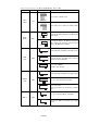
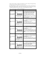
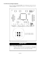
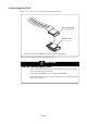
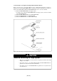
Table Of Contents
- Preface
- Contents
- 1. Precautions for Safety
- 2. Preparation
- 3. Setting Up
- 3.1 Selecting Clock Supply
- 3.2 Using an Internal Oscillator Circuit Board
- 3.3 Using the Oscillator Circuit on the Target System
- 3.4 Using the Internal Oscillator Circuit
- 3.5 Setting Switches
- 3.6 A-D Conversion Bypass Capacitor
- 3.7 Connecting the PC7501
- 3.8 Connecting the Target System
- (1) Connecting to a 100-pin LCC Socket
- (2) Connecting to a 100-pin 0.65-mm-pitch Foot Pattern (Part 1)
- (3) Connecting to a 100-pin 0.65-mm-pitch Foot Pattern (Part 2)
- (4) Connecting to a 100-pin 0.65-mm-pitch Foot Pattern (Part 3)
- (5) Connecting to a 100-pin 0.5-mm-pitch Foot Pattern (Part 1)
- (6) Connecting to a 100-pin 0.5-mm-pitch Foot Pattern (Part 2)
- (7) Connecting to a 100-pin 0.5-mm-pitch Foot Pattern (Part 3)
- (8) Connecting to a 144-pin 0.5-mm-pitch Foot Pattern
- 4. Usage
- 5. Specifications
- 6. Troubleshooting
- 7. Maintenance and Guarantee
( 38 / 76 )
(1) Connecting to a 100-pin LCC Socket
When connecting the emulation probe to a 100-pin LCC socket (Yamaichi Electronics Co., Ltd.:
IC61-1004-051 etc.) on the target system, following the procedure below.
(1) Attach the CN2 side of the M30850T-EPB to the CN2 side of the M30800T-PTC.
(2) Attach the M30800T-PTC to the 100-pin LCC socket.
Figure 3.11 Connecting to a 100-pin LCC socket
CAUTION
Notes on Connecting the Target System:
• Take care not to attach the converter board in a wrong direction. It may cause a fatal
damage to the emulator.
• The small connectors of the M30800T-PTC are guaranteed for only 50 insertion/
removal iterations.
• For purchasing the IC61-1004-051 or for technical information, contact Yamaichi
Electronics Co., Ltd.
http://www.yamaichi.co.jp/e/index.shtml