Access Control Design Guide An engineer's guide for planning and installing a Symmetry™ Access Control System using M2150 Controllers MAN-M2150/ENG (9600-0420)
© G4S Technology 2009 All rights reserved. No part of this publication may be reproduced in any form without the written permission of G4S Technology Limited. G4S Technology Limited cannot be held liable for technical and editorial omissions or errors made herein; nor for incidental or consequential damages resulting from the furnishing, performance or use of this material.
Contents 1 Preface ................................................................................................. v About this Guide ............................................................................................................................ v Underwrites Laboratories (UL) Compliance .................................................................................. v M2150 Installation Instructions ..........................................................................................
Contents Specifying the Door Furniture ...................................................................................... 24 Power for Door Releases ............................................................................................................ 24 Using Noise Suppression ............................................................................................................ 24 Choosing Cable Supervision ...................................................................................
1 Preface About this Guide This guide is a document for people who need to design or install Symmetry M2150 systems. The manual gives: • An overview of Symmetry and the M2150 hardware. • Design, planning and installation advice. • Test and maintenance procedures. • System specifications. It is recommended people new to M2150 read this guide.
Preface M2150 ENC1 Installation Instructions (9600-0493) (NOT EVALUATED BY UL) M2150 ENC3 Installation Instructions (9600-0495) (NOT EVALUATED BY UL) M2150 ENC4 Installation Instructions (9600-0496) (NOT EVALUATED BY UL) ENVS Installation Instructions (9600-0431) (NOT EVALUATED BY UL) AC24/4 Alarms controller Installation Instructions (24IN-4OUT) (9600-0492) (UL LISTED) OC4/24 Alarms controller Installation Instructions (4IN-24OUT) (9600-0465) (UL LISTED) Elevator Controller (Master Unit) Installation Inst
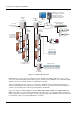
1 Chapter 1: Introduction to Symmetry and M2150 About Symmetry Symmetry is a security management system that provides a single integrated solution for all key elements of site security, including access control, intruder detection, guard patrolling, intercom management, CCTV monitoring, video recording and video playback.
Introduction to Symmetry and M2150 Standalone or networked PCs running the Security Management System Software (used for system setup and monitoring). Database Unit (e.g. 4DBC) Database Unit (e.g. DBU) Up to 32 database units in chain Wired or wireless comms Edge Network Video Server (ENVS) LAN/WAN Door Controller (e.g. 2DC) Door Controller (e.g.
Introduction to Symmetry and M2150 A database unit and all the controllers that are connected to it is collectively known as a "node". An elevator node is available that can control access to 64 elevator floors and four cabs. The node contains an Elevator Interface Board, which is a controller that enables the elevator readers and other hardware, such as floor buttons, to be connected.
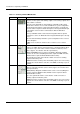
Introduction to Symmetry and M2150 Table 1-1: Summary of M2150 Main Boards Device DBU Picture Purpose A database unit that allows autonomous operation of up to 16 readers. Readers, monitor points and auxiliary outputs connect using separate door and/or alarms controllers. The unit can be fitted with an optional NIC-4 or NIC-WI module, which allows LAN or wireless access from an SMS PC for system configuration, monitoring and reporting.
Introduction to Symmetry and M2150 8DBC This is a combined database unit and door controller for up to eight readers and associated door furniture (release device, bypass, door monitor and exit request button). 20mA (MCLP) or Wiegand readers can be connected (Wiegand readers require the WIM-8 module). An optional I/O module can be fitted to enable connection of auxiliary outputs and monitor points.
Introduction to Symmetry and M2150 A four-camera digital video server (see page 26). ENVS Table 1-2: M2150 Optional Modules Device One-Port RS232 module Picture Purpose A module (MN-232-1) that mounts onto a database unit to enable use of a fall-back modem, bi-directional communications with an SMS PC, or communications with a serial device such as an ENVS. The module is necessary only if the integrated RS232 port is in use.
Introduction to Symmetry and M2150 Examples of Equipment Use Table 1-3 gives examples of the maximum number of readers, auxiliary outputs and monitor points that are available with different combinations of equipment. The table shows a small sample of possible configurations.
2 Chapter 2: Designing and Planning an M2150 System About this Chapter This chapter explains the issues to consider during system design, planning and installation.
Designing and Planning an M2150 System cables to readers and door furniture and therefore the cost of installing the equipment. When choosing the number and type of database units and door controllers, consider the locations of the readers and the total cost of installing the equipment, not just the cost of the hardware. Using Chains for System Expansion When more than one database unit is required, a common practice is to fit a NIC module to each database unit.
Designing and Planning an M2150 System Power for Auxiliary Outputs In most cases, power for auxiliary outputs can be sourced from the controller's internal power supply unit. You will need to make sure that the power supply is able to provide sufficient current for all required devices. The section on page 27 explains how to do this.
Designing and Planning an M2150 System Note: • Antipassback can have an impact on the number of database units required. If the site is to use antipassback rules, please refer to the section on page 20. • Each elevator to be access controlled requires a separate DBU in an elevator node (see page 14). Specifying the Address of a Door or Alarms Controller Each door and alarms controller connected to the same database unit must have a unique address, which should be marked on the Site Schematic.
Designing and Planning an M2150 System Table 2-1: Port Usage Configurations First (or only) database unit in chain 2 3 4 5 Database units between first and last5 COM C RS232/ Modem to PC Fall-back 2 modem Serial 1 Device Serial 1 Device Bi-directional RS232 4 Comms Serial 1 Device Serial 1 Device COM D Serial 1 Device LAN (NIC 4 or NIC-WI to PC) LAN (NIC 4 or NIC-WI to PC) LAN (NIC 4 or to PC) Serial 1 Device Bi-directional RS232 4 Comms - COM E - Serial 1 Device Fall-back 2 modem
Designing and Planning an M2150 System Determine whether this level of communications security is necessary. The decision may be based on any history of network interruptions and whether the network architecture could accommodate two network paths to SMS PCs. The feature is not applicable to other NIC modules, such as the NIC-WI. Each NIC4 module requires a separate IP address. Note: Only one LAN chain needs to be defined in the SMS software.
Designing and Planning an M2150 System Planning for Elevator Control The elevator controller is an M2150 node that can be used to control access to elevator floors. The node interfaces with the elevator control system and floor-selection panel to ensure that the card holder is delivered only to authorized floors. The node supports up to: • 64 floors for a single-cab system. For more than 32 floors, a slave unit is also required. • 32 floors for a two-cab system (32 floors per cab).
Designing and Planning an M2150 System floor is in the card holder's access rights, the appropriate floor relay in the node is de-energized (COM to NC contacts made) and further transactions are inhibited for the length of time specified by the reader's Floor Selection Time. Note: In the SMS Software, the elevator node Floor Selection option must be set to Individual to activate Enable Select mode.
Designing and Planning an M2150 System Free/Secure Relay Each relay board in the elevator node includes a free/secure relay, which is energized if any of the floors controlled by that relay board is in Secure Access mode. The relay is deenergized when all floors are in Free Access mode. This could be used by an external device to indicate the current access status. During system planning, determine whether this feature is required.
Designing and Planning an M2150 System Safety The elevator node may have mains electricity connected to the floor relays. Power to the floor relays must be disconnected before carrying out any installation or servicing work. Make sure that installers are aware of this safety issue. Mains wiring must be carried out only by a competent installer. The equipment must be grounded. In some localities, there are union affiliations or certifications required to work on elevator systems.
Designing and Planning an M2150 System Choosing the Cabinets This section explains the standard cabinets/enclosures available for M2150 systems. There are two main cabinet types: ones that have a hinged door (CAB3A, CAB4A and CAB5 ), and others that have a removable lid (ENC-1, ENC3 and ENC4). There is also a RAK3, which is a 19" rack-mountable cabinet. Note: Only the CAB3A and CAB4A can be used for installations that require compliance with UL294.
Designing and Planning an M2150 System ENC-1L The ENC-1L is available only for certain markets. It can contain a 32Vac power supply unit (MN-PSU-2+2), two 12Vdc backup batteries and the following: • One 8DBC, 4DBC, 2DBC, 4DCN, 4DC, AC24/4 or OC4/24 • One or two 2DCs. ENC-1 The ENC-1 can contain any of the following, with a 3.0A (MN-PSU-KIT; 7000-5283) 12Vdc power supply unit: • One ENVS, 8DBC, 4DBC, 2DBC, 4DCN, 4DC, AC24/4 or OC4/24 • One or two 2DCs.
Designing and Planning an M2150 System Planning Antipassback Note: You need to read this section only if the site requires antipassback rules. Installation and planning is made easier if antipassback is not required. If antipassback is required, consider the type of antipassback required: zonal or timed. Timed is easier to set up, but is not quite as secure as zonal.
Designing and Planning an M2150 System The system remembers which zone each card is in and updates this information whenever the card is used at a zonal antipassback reader. An antipassback alarm or event is generated if the reader's from zone does not match the card's currently-recorded zone. For example, an alarm or event is generated if the from zone of the reader is zone 3, but the card is currently recorded as being in zone 1.
Designing and Planning an M2150 System Selecting the Readers Select the type of reader to be used for each access-controlled door. Magnetic stripe, proximity, smart card and fingerprint readers are available. All are easy to use and install, and are available in a number of attractive designs. M2150 supports 20mA multiNODE Current Loop Protocol (MCLP), Wiegand and RS485 readers.
Designing and Planning an M2150 System Planning the Reader Locations Specify the type, model and location of each reader, the door it is to control and the cable routing path between the reader and door controller. Check the locations during a site survey. Readers need to be located on the unhinged side of the door, and away from desks or other items that could make access difficult. Specify the position and height of each reader. The normal height for standard card readers is approximately 5' (1.
Designing and Planning an M2150 System Specifying the Door Furniture The door furniture (Figure 2-3) can consist of a release device, door monitor, exit-request button/sensor and bypass circuit. The exit-request button and bypass circuit are optional. The bypass circuit enables a device such as an alarm sensor to be automatically bypassed while the lock is released.
Designing and Planning an M2150 System Inductive load, e.g. electric lock or striking plate Cathode IN4004 Anode Figure 2-4: Connecting a Noise Suppression Diode Choosing Cable Supervision The cables to the door monitors and exit-request buttons can be supervised for short and open circuits, as described on page 31. Determine the level of cable supervision that the customer requires, and make sure that the correct resistors will be available to the installer.
Designing and Planning an M2150 System Using an Edge Network Video Server (ENVS) An ENVS is a network device for recording and streaming video from up to four connected cameras. An ENVS can be fitted inside the same cabinet as a database unit or controller, or can be a standalone or rack-mounted device. When the optional hard disk is fitted, a store-and-forward function allows video to be recorded locally, then forwarded over a network to a storage location during out-of-hours times.
Designing and Planning an M2150 System Considering the Power and Ground Requirements Introduction Power can be provided by an power supply mounted in the cabinet, as follows: • For ENC3, ENC4, CAB3A, CAB4A and CAB5: Two power supplies are available: − MN-PSU-6A. This can supply a maximum of 6.5A @ 12Vdc. 6A is available to power the board, readers, etc. A separate output provides up to 500mA for battery recharge.
Designing and Planning an M2150 System Table 2-3: 12Vdc Current Available for Readers, ENVS, Door Releases and Auxiliary Outputs Device 8DBC 4DBC 2DBC 8DC 4DC 4DCN 2DC AC24/4 Alarms controller (24IN-4OUT) OC4/24 Alarms controller (4IN-24OUT) Elevator node 12Vdc Available Current (mA) 2 1 6.5A PSU 3.5A PSU 3.0A PSU 2.
Designing and Planning an M2150 System Table 2-4: Device-Level Power Consumption Device 8DBC PCB, excluding relays 4DBC PCB, excluding relays 2DBC PCB, excluding relays DBU PCB AC24/4 Alarms controller (24IN-4OUT), excluding relays OC4/24 Alarms controller (4IN-24OUT), excluding relays 8DC PCB, excluding relays 4DC PCB, excluding relays 4DCN PCB, excluding relays 2DC PCB, excluding relays 8IN-4OUT I/O Module PCB 4IN-8OUT I/O Module PCB Each energized On 8IN-4OUT I/O module and AC24/4 auxiliary output, Alar
Designing and Planning an M2150 System Determining the Cable and Wiring Requirements Table 2-5 shows the recommended cable types and maximum distances. It is important to check that the planned cable routes will not cause these distances to be exceeded. Table 2-5: Cable Types and Maximum Distances Item to be Connected Max.
Designing and Planning an M2150 System Cable Supervision Determine the level of cable supervision required for cables to door monitors, exit-request buttons and monitor points. This allows short-circuit, open-circuit and tamper conditions to be detected, depending on the termination resistors added to the end of the cable (i.e. as near as possible to the monitor-point contact, etc.). The SMS software can generate an alarm or event for any cable fault or tamper condition.
Designing and Planning an M2150 System Six-State Supervision Six-state supervision is applicable to monitor points connected to: • Alarms controllers. • 4in-8out or 8in-4out I/O modules fitted to M2150 controllers/database units with v3.0 or later firmware. Six-state supervision allows the status of a sensor tamper switch to be monitored, as well as both shortcircuits and open-circuits on the cable. Six-state supervision uses the cable termination shown in Figure 2-8.
Designing and Planning an M2150 System Planning the SMS Software and PC Requirements Selecting the SMS Software Edition It is necessary to select one of four editions of the SMS software to use: Business, Professional, Enterprise or Global, as described in the following sections. The software edition selected must be appropriate for the size and requirements of the system being installed. Version 6.1 SP2 or later of the SMS software must be used.
Designing and Planning an M2150 System Region 0 (Head Office) Server (holds local databases) Access-control equipment is connected to each regional system in the normal way.
Designing and Planning an M2150 System The Global edition architecture provides the ultimate resilience for multi-site applications. Any failure of the corporate network links still allows autonomous systems to continue operating fully at a local level. The Central Card Handler database can be located on the head office server or on another machine.
Designing and Planning an M2150 System Most installations use the standard Administration Client software, which gives access to all screens of the SMS software (depending on operator permissions and the options purchased). However, for specialist purposes, the following client types are also available: • Alarm Client – An Enterprise or Global edition client that can be used only to display the View/Alarms screen for acknowledgment and clearing of alarms.
Designing and Planning an M2150 System Installation Requirements Before installing an M2150 system, all installers should be made aware of the following. UL Requirements Ensure that all installers are familiar with UL installation requirements, as given in Appendix B on page 54. Shielded Cable (Screens) To avoid multiple paths to ground, cable shields must be connected only as shown in the installation instructions.
A Appendix A Maintenance and Test Procedures General Procedures The only item that requires regular testing and maintenance is the 7AH backup battery (not available for RAK3). It is recommended that the battery in each unit is tested at least once a year by disconnecting its external power supply and checking that the unit continues to operate normally for the period of time specified in the Service Contract. This equipment is to be installed indoors only (except readers that specify otherwise).
Maintenance and Test Procedures LED12 (12V) – Illuminated when the 12Vdc supply is connected. LED13/17 (RX) – Illuminated when receiving data from a 20mA reader (off for Wiegand). LED14/18 (TX) – Illuminated when transmitting data to a 20mA reader (off for Wiegand). LED15/19 (BY) – Illuminated when the bypass relay is energized. LED16/20 (RL) – Illuminated when the release relay is energized. LED21 (NIC2 Tx) – Illuminated when transmitting data to the plug-in COM E port.
Maintenance and Test Procedures LED10 (DC COMMS) – Illuminated when an external door or alarms controller is connected. LED11/12/13/14 (RDR 1/2/3/4) – Illuminated when the reader is connected properly. LED19 (NIC1 Rx) – Illuminated when receiving data from the plug-in COM D port. LED20 (NIC1 Tx) – Illuminated when transmitting data to the plug-in COM D port. LED21 (NIC2 Rx) – Illuminated when receiving data from the plug-in COM E port.
Maintenance and Test Procedures LED52 (RS232 RX) – Flashes when the on-board RS232 port (TB15) is receiving data. Otherwise, the LED is not illuminated. LED53 (RS485 TX) – Illuminated when transmitting data to an external door or alarms controller. LED54 (RS485 RX) – Illuminated when receiving data from an external door or alarms controller. LED17/19 (COM D/E RX) – Illuminated when receiving data from the plug-in COM D/E port.
Maintenance and Test Procedures LED15 (12V) – Illuminated when the 12Vdc supply is connected. LED16 (5V) – Illuminated when the on-board 5Vdc supply is operating. LED17 (3V) – Illuminated when the on-board 3Vdc supply is operating. LEDs on the 4DC LED1/2/3/4 (READERS OK 2/3/1/4) – Illuminated when the reader is connected properly. LED5/11/20/26 (Rx) – Illuminated when receiving data from a 20mA reader (off for Wiegand).
Maintenance and Test Procedures LEDs on the AC24/4 Alarms Controller LED1 (OK) – When the controller is functioning correctly, this should flash at two-second intervals (one second on and one second off). LED2 (DATA Tx) – Illuminated when transmitting data to a database unit. LED3 (DATA Rx) – Illuminated when receiving data from a database unit. LED4 (POWER) – Lit steadily while power is applied. LEDs on the DBU LED1/3 (COMA/B RX) – Flashes when there is a database unit connected to the COM A/B port.
Maintenance and Test Procedures LEDs on the Elevator Interface Board LED1 (OK) – When the board is functioning correctly, this should flash at two-second intervals (one second on and one second off). LED2 (Data Tx) – Illuminated when transmitting data. LED3 (Data Rx) – Illuminated when receiving data. LED4 (PWR) – Lit steadily while power is applied. LED5/7/9/11 (Reader 1/2/3/4 Tx) – Illuminated when transmitting data to a 20mA reader (not applicable to slave unit).
Maintenance and Test Procedures Performing a Warm or Cold Reset If an operational problem is encountered, a warm reset of a database unit can be achieved by pressing then immediately releasing the reset button. A warm reset restarts the processor. It does not clear data from the database unit, such as card and other data that has been downloaded from the SMS software. A cold reset can be achieved by pressing then holding down the reset button for five seconds.
Maintenance and Test Procedures Installing the Renesas Flash Development Toolkit To install the Renesas Flash Development Toolkit: 1. Go to www.renesas.com, and select your region. 2. Enter the search string "Flash Development Toolkit" and click the first result. 3. Click Downloads. 4. Search for the evaluation version of the Flash Development Toolkit, v3.07, and download it to your computer. 5. Double-click the downloaded exe file, and follow the prompts. Accept all defaults.
Maintenance and Test Procedures Select the COM port that the programming device is connected to. Click OK. Make sure Selecting Device shows HD64F2378, then click OK when all sections have a check mark.
Maintenance and Test Procedures Change the CPU crystal frequency setting to 20. Change the multiplier setting to 1. Remove the checkmark. Select 57600 from the drop-down list.
Maintenance and Test Procedures Keep the defaults. Select the options shown here. You are now ready to download a firmware file, as described next.
Maintenance and Test Procedures Updating Firmware Using the Flash Development Toolkit Once the toolkit has been configured, it can be used to download a firmware file to the database unit/controller. If the FDT Simple Interface dialog is not already displayed, select Flash Development Toolkit 3.07 Basic from the Windows Start menu. Place a checkmark in the User/Data Area checkbox, then select the firmware file to download using the Browse button.
Maintenance and Test Procedures To use Flash2100: 1. If you are going to use Flash2100 at an SMS client PC, shut down the SMS service named SMS Client Services at the PC. You can do this as follows: a) Check whether the SMS Service Monitor icon is displayed in the System Tray (normally, in the bottom-right corner of the screen): b) If the icon is displayed, double-click the icon, select SMS Client Services, and click Stop.
Maintenance and Test Procedures 4. Select the communications settings to the database unit. If you are using serial communications, the Baud rate must be the same as set at the database unit (normally 9600). Leave Other Options at the default settings (as shown in the picture). 5. Click Search, then select the DCU radio button. The following shows an example of the information displayed. The tree on the left side of the screen lists each database unit and controller found.
Maintenance and Test Procedures This shows the cumulative total number of controller addresses used. This represents a door controller. This represents an alarms controller. The right side of the screen lists the firmware and current status of each database unit/controller. The status information will change when you begin a firmware download. 6. Select the device you want to download firmware to by selecting the appropriate item on the right side of the screen. The device is highlighted in the tree.
B Appendix B Underwriters Laboratories (UL) Compliance Installers and sales representatives should familiarize themselves with the requirements of this section in order to form a better understanding of the requirements for installing this equipment in a UL Listed environment.
Underwriters Laboratories (UL) Compliance Power-Limited Wiring UL compliance requires power-limited and non-power-limited wiring to be separated by at least 0.25” (7mm). Any additional power supply used (e.g. for door releases and auxiliary outputs) must be power limited, UL Listed for Access Control Systems and Accessories. The recommended cable routing diagrams in the cabinet installation instructions show power-limited and non-power limited wiring.
C Appendix C: M2150 Specifications Electrical MN-PSU-6A power supply: Input is 19-20Vac or 24Vdc @ 150VA max. Output is 6.5A @12Vdc max (6A for system power and 500mA for battery). Use only MN-TRANS-150-UL 19Vac transformer for UL294 applications. MN-PSU-KIT (7000-5283) power supply: Input is 18Vac or 24Vdc @ 75VA max. Output is 3.0A @12Vdc max (2.5A for system power and 500mA for battery). Use only MN-TRANS-75-UL 18Vac transformer for UL294 applications.
M2150 Specifications Elevator Node: 20" (508mm) height, 20" (508mm) width, 6.6" (168mm) depth. ENC-1L: 15 3/4" (400mm) height, 19.1/8" (485mm) width, 4 1/8" (106mm) depth. Key type for CAB3A/CAB4A/RAK3/CAB5: Standard "service" key.
M2150 Specifications Table A-2: Reader Currents Reader Model S620 Current Consumption at 8.89-13.49Vdc 100mA S635 100mA S640 50mA S670 100mA S671 100mA S680 100mA S682 100mA S710 150mA S711 150mA S820 100mA S821 110mA S822 210mA S830 85mA S831 100mA S840 100mA S841 150mA S842 280mA S843 MKII 190mA S844 180mA S853 195mA Evaluated by UL Note: The mark indicates that the model is suitable for use with M2150 UL294 applications.
D Appendix D: Site Schematic Check List This appendix lists the items that should be marked on the Site Schematic (see page 8).
Site Schematic Check List The backup power source for each cabinet (normally a 12V 7AH battery) Where to ground each cabinet Cable supervision level for monitor points Details of any additional power supplies required for auxiliary outputs Elevator Nodes (if used) For each elevator node, mark the following: The locations of the master and slave units.
Site Schematic Check List The door/elevator it is to control Cable type and routing path to the controller The port to be used for an RS485 reader (if applicable) Two readers at one door: the location of the paired reader (if applicable), and the port number to use at the door controller Door Furniture For each access-controlled door, mark the following: Position of any required exit-request button Whether a bypass circuit is needed Details of any special noise-suppression circuitry
E Index 2 2DBC ......................................................................................................................................... See Database unit 2DC .......................................................................................................................................... See Door controller 4 4DBC ......................................................................................................................................... See Database unit 4DC ...........
Index Fall-back.......................................................................................................................................................... 13 Ports ................................................................................................................................................................ 11 Primary/secondary ..........................................................................................................................................
Index F Fall-back communications................................................................................................................................... 13 Fireman's switch.................................................................................................................................................. 17 Firmware .............................................................................................................................................................
Index OC4/8 ............................................................................................................................................. See I/O module Optional modules .............................................................................................................................................. 3, 6 P Pan, tilt, zoom .....................................................................................................................................................
Index Symmetry .............................................................................................................................................................. 1 T Tamper ................................................................................................................................................................ 32 Tenant security .................................................................................................................................................