
Instruction manual


Designing and Planning an M2150 System
Access Control Design Guide
9
cables to readers and door furniture and therefore the cost of installing the equipment. When choosing the
number and type of database units and door controllers, consider the locations of the readers and the total
cost of installing the equipment, not just the cost of the hardware.
Using Chains for System Expansion
When more than one database unit is required, a common practice is to fit a NIC module to each database
unit. This allows each database unit to connect independently to the network. If network sockets are
provided throughout a building, this may be a convenient method of enabling communications between the
database units and the PCs running the SMS software. However, a more cost-effective solution may be to
use a "chain" of database units.
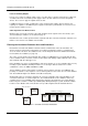
In a chain, a cable of up to 3000ft (1km) connects each database unit to the next (the COM B port
connects to the COM A port of the next database unit in the chain). Only the first database unit in the chain
requires a network or serial communications link to an SMS PC. For network communications, this means
that only one NIC module needs to be purchased, and only one IP address needs to be used. For serial
communications, the benefit is that additional COM ports do not need to be provided at SMS PCs.
A chain can contain up to 32 database units. Each database unit requires a unique address in the range 1
to 32, which is set using bit switches on the PCB.
You can connect an M2150 database unit to an existing multiNODE chain. It cannot be connected to a
legacy Micronode chain. A multiNODE-2 or M2000 cannot be connected to a newly-defined M2150 chain.
Symmetry has a limit of 1024 LAN chains. The chains must contain more than one database unit in large
installations that require more than 1024 LAN-connected database units.
Monitor Points, Auxiliary Outputs and Alarms Controllers
Determine the number of any monitor points and auxiliary outputs that are required, mark this information
on the Site Schematic, then consider how to provide them. There are two choices: using I/O modules or
alarms controllers.
An I/O module normally gives a cost-effective method of providing monitor points and auxiliary outputs,
since the module simply slots into a socket on the PCB of a database unit or door controller. This means
that no separate cabinet or power supply is needed. Most database units and door controllers have at least
one socket for an I/O module – refer to Table 1-1 on page 4 for details.
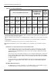
An I/O module provides up to eight monitor points and four auxiliary outputs, or four monitor points and
eight auxiliary outputs, depending on the module selected (see Table 1-2 on page 6).
If there is a requirement for a large number of monitor points or auxiliary outputs, connecting separate
alarms controllers to the database unit may be a better solution. However, each alarms controller reduces
the number of readers that the database unit can manage by four.
There are two alarms controllers: the AC24/4 has 24 monitor points and four auxiliary outputs, and the
OC4/24 has four monitor points and 24 auxiliary outputs.
Alarms controllers connect to a database unit or other controller in exactly the same way as a door
controller. Therefore, multidrop and star connection topology can be used, with the same maximum length
of cable. Any combination of door and/or alarm controllers can connect to a database unit, providing the
number of controller addresses used does not exceed eight.