To our customers, Old Company Name in Catalogs and Other Documents On April 1st, 2010, NEC Electronics Corporation merged with Renesas Technology Corporation, and Renesas Electronics Corporation took over all the business of both companies. Therefore, although the old company name remains in this document, it is a valid Renesas Electronics document. We appreciate your understanding. Renesas Electronics website: http://www.renesas.
Notice 1. 2. 3. 4. 5. 6. 7. All information included in this document is current as of the date this document is issued. Such information, however, is subject to change without any prior notice. Before purchasing or using any Renesas Electronics products listed herein, please confirm the latest product information with a Renesas Electronics sales office.
User’s Manual SH7144 Group FP-112B User System Interface Board HS7144ECH61H User’s Manual Renesas Microcomputer Development Environment System SuperH™ Family/SH7144 Series Rev.4.0 2004.
Cautions Keep safety first in your circuit designs! 1. Renesas Technology Corp. puts the maximum effort into making semiconductor products better and more reliable, but there is always the possibility that trouble may occur with them. Trouble with semiconductors may lead to personal injury, fire or property damage.
IMPORTANT INFORMATION READ FIRST • READ this user's manual before using this user system interface cable. • KEEP the user's manual handy for future reference. Do not attempt to use the user system interface cable until you fully understand its mechanism. User System Interface Cable: Throughout this document, the term "user system interface cable" shall be defined as the following product produced only by Renesas Technology Corp. excluding all subsidiary products.
LIMITED WARRANTY Renesas warrants its user system interface cables to be manufactured in accordance with published specifications and free from defects in material and/or workmanship. Renesas will repair or replace any user system interface cables determined to be defective in material and/or workmanship. User system interface cables are wearing parts which Renesas will not repair or replace if damaged and/or worn through use.
State Law: Some states do not allow the exclusion or limitation of implied warranties or liability for incidental or consequential damages, so the above limitation or exclusion may not apply to you. This warranty gives you specific legal rights, and you may have other rights which may vary from state to state.
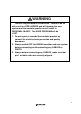
SAFETY PAGE READ FIRST • READ this user's manual before using this user system interface cable. • KEEP the user's manual handy for future reference. Do not attempt to use the user system interface cable until you fully understand its mechanism. DEFINITION OF SIGNAL WORDS This is the safety alert symbol. It is used to alert you to potential personal injury hazards. Obey all safety messages that follow this symbol to avoid possible injury or death.
WARNING Observe the precautions listed below. Failure to do so will result in a FIRE HAZARD and will damage the user system and the emulator product or will result in PERSONAL INJURY. The USER PROGRAM will be LOST. 1. Do not repair or remodel the emulator product by yourself for electric shock prevention and quality assurance. 2. Always switch OFF the E6000H emulator and user system before connecting or disconnecting any CABLES or PARTS. 3.
Preface The HS7144ECH61H is a user system interface board that connects a user system for the SH7144 FP-112B package to the SH7046 E6000H emulator (HS7046EPH60H).
Contents Section 1 Configuration.....................................................................................1 Section 2 Environmental Conditions.................................................................3 2.1 Setting Operating Voltage and Operating Frequency ....................................................... 3 Section 3 Product Specifications .......................................................................4 Drop in Vcc Level Detection Function: ..................................
Section 1 Configuration Figure 1 and table 1 show the configuration and components of the user system interface board for the FP-112B package. Please make sure you have all of these components when unpacking. EV-chip board Screws (M2.0 x 8 mm) with flat washers Screws (M2.
CAUTION Use an IC149-112C15333-0B socket (manufactured by YAMAICHI ELECTRONICS Co., Ltd.) for the FP-112B package IC socket on the user system. Table 1 HS7144ECH61H Components No. Component Quantity Remarks 1 Board 1 With two spacers (2.6MP x 6 mm) 2 IC socket 1 For the FP-112B package (to be mounted on the user system) 3 Socket cover 1 For the FP-112B package (for installing MCU) 4 Screws (M2.0 x 12 mm) 4 For fastening board (with four flat washers) 5 Screws (M2.
Section 2 Environmental Conditions Maintain the conditions in table 2 when using the emulator. Table 2 Environmental Conditions Item Specifications Temperature Operating: +10 to +35°C Storage: -10 to +35°C Humidity Operating: 35 to 80% RH, no condensation Storage: 35 to 80% RH, no condensation Vibration Operating: 2.45 m/s max. Storage: 4.9 m/s max. Transportation: 14.7 m/s max. Ambient gases There must be no corrosive gases present. 2.
Section 3 Product Specifications The specifications of this product are shown in table 3. Table 3 Product Specifications Item Specifications Target processor SH7144F Package FP-112B Function Level limitation: This function keeps the output signal from 3-V emulator system equal to or less than power supply voltage of the user system (Vcc). User-system operating conditions Power supply voltage Vcc: 3.0 to 3.
Section 4 User Interface Specifications The user system interface board incorporates a level conversion circuit supporting a low-voltage circuit. Accordingly, when connecting the user system to the emulator, pay attention to the signal delays and the number of FANINs and FANOUTs. 4.1 User System Interface Circuit The user system interface circuit of the user system interface board is shown below.
(3) AVcc and AN7 to AN0 5Vcc QS3384 AN7 to AN0 Emulator Vss User system AVss Figure 5 User System Interface Circuit for AVcc and AN7 to AN0 6
Section 5 Connection Procedures 5.1 Connecting User System Interface Board to User System WARNING Always switch OFF the user system and the emulator product before the USER SYSTEM INTERFACE BOARD is connected to or removed from any part. Before connecting, make sure that pin 1 on both sides are correctly aligned. Failure to do so will result in a FIRE HAZARD and will damage the user system and the emulator product or will result in PERSONAL INJURY. The USER PROGRAM will be LOST.
5.1.2 Installing Cable Head CAUTION Check the location of pin 1 before inserting. Align pin 1 on the IC socket for an FP-112B package on the user system with pin 1 on the user system interface board, and insert the user system interface board into the IC socket on the user system, as shown in figure 6. 5.1.3 Fastening Cable Head CAUTION 1. Use a Phillip-type screwdriver whose head matches the screw head. 2. The tightening torque must be 0.098 N•m or less.
Screws (M2.0 x 12 mm) with flat washers Board Pin 1 User system IC socket (IC149-112C15333-0B manufactured by YAMAICHI ELECTRONICS Co., Ltd.
5.2 Connecting User System Interface Board to EV-Chip Board WARNING Observe the precautions listed below. Failure to do so will result in a FIRE HAZARD and will damage the user system and the emulator product or will result in PERSONAL INJURY. The USER PROGRAM will be LOST. 1. Always switch OFF the user system and the emulator product before the USER SYSTEM INTERFACE BOARD is connected to or removed from any part. Before connecting, make sure that pin 1 on both sides are correctly aligned. 2.
EV-chip board Connector No. EV-Chip Board Connector No. Board Connector No.
5.3 Recommended Dimensions for User System Mount Pad (Footprint) Figure 8 shows the recommended dimensions for the mount pad (footprint) for the user system with an IC socket for an FP-112B package (IC149-112C15333-0B: manufactured by YAMAICHI ELECTRONICS Co., Ltd.). Note that the dimensions in figure 8 are somewhat different from those of the actual chip's mount pad.
5.4 Dimensions for EV-Chip Board and User System Interface Board The dimensions for the EV-chip board and the user system interface board are shown in figure 9. 116.0 140.0 EV-chip board 100.0 31.0 33.5 16.0 34.5 69.0 92.0 29.5 5.0 19.5 User system interface board Spacer Unit: mm Tolerance: ±0.
5.5 Resulting Dimensions after Connecting User System Interface Board The resulting dimensions, after connecting the user system interface board to the user system, are shown in figure 10. 31.0 Spacer (φ6.0) 14.0 12.3 36.0 61.0 EV-chip board IC socket (IC149-112C15333-0B manufactured by User system YAMAICHI ELECTRONICS Co., Ltd.) 29.5 29.5 31.0 Unit: mm Tolerance: ±1.
Section 6 Installing the MCU to the User System CAUTION 1. Check the location of pin 1 before inserting. 2. Use a Philips-type screwdriver whose head matches the screw head. 3. The tightening torque must be 0.098 N•m or less. If the applied torque cannot be accurately measured, stop tightening when the force required to turn the screw becomes significantly greater than that needed when first tightening.
Screws (M2.0 x 8 mm) with flat washers Socket cover MCU (SH7144) Pin 1 IC socket (IC149-112C15333-0B manufactured by YAMAICHI ELECTRONICS Co., Ltd.
Section 7 Verifying Operation 1. Turn on the emulator according to the procedures described in the SH7046 E6000H Emulator User's Manual (HS7046EPH60HE). 2. Verify the user system interface cable connections by checking the pin states with the extended monitor and checking the bus states with the FILL command (emulator command). If an error is detected, recheck the soldered IC socket and the location of pin 1. 3.
To use the crystal oscillator mounted on the EV-chip board Install a crystal oscillator into the crystal oscillator terminals on the EV-chip board.
Section 8 Notice 1. Before connecting any parts or cables, make sure that pin 1 on the both sides are correctly aligned. 2. Do not apply excessive force to the user system interface board while it is connected to the user system. 3. The dimensions of the recommended mount pad for the IC socket for this user system interface board are different from those of the MCU. 4. This user system interface board is specifically designed for the HS7046EPH60H emulator.
SH7144 Group FP-112B User System Interface Board HS7144ECH61H User's Manual Publication Date: Rev.4.00, January 29, 2004 Published by: Sales Strategic Planning Div. Renesas Technology Corp. Edited by: Technical Documentation & Information Department Renesas Kodaira Semiconductor Co., Ltd. 2004 Renesas Technology Corp. All rights reserved. Printed in Japan.
SH7144 Group FP-112B User System Interface Board HS7144ECH61H User’s Manual 1753, Shimonumabe, Nakahara-ku, Kawasaki-shi, Kanagawa 211-8668 Japan REJ10B0038-0400H