To our customers, Old Company Name in Catalogs and Other Documents On April 1st, 2010, NEC Electronics Corporation merged with Renesas Technology Corporation, and Renesas Electronics Corporation took over all the business of both companies. Therefore, although the old company name remains in this document, it is a valid Renesas Electronics document. We appreciate your understanding. Renesas Electronics website: http://www.renesas.
Notice 1. 2. 3. 4. 5. 6. 7. All information included in this document is current as of the date this document is issued. Such information, however, is subject to change without any prior notice. Before purchasing or using any Renesas Electronics products listed herein, please confirm the latest product information with a Renesas Electronics sales office.
User’s Manual SH7058 Group FP-256H User System Interface Board HS7058ECF61H User’s Manual Renesas Microcomputer Development Environment System SuperH™ Family/SH7050 Series Rev.6.0 2004.
Cautions Keep safety first in your circuit designs! 1. Renesas Technology Corp. puts the maximum effort into making semiconductor products better and more reliable, but there is always the possibility that trouble may occur with them. Trouble with semiconductors may lead to personal injury, fire or property damage.
Preface The HS7058ECF61H is a user system interface board that connects a user system for the SH7058 FP-256H package to the SH7058 E6000H emulator (HS7058EPH60H).
Contents Section 1 Configuration.....................................................................................1 Section 2 Connection Procedures ......................................................................3 2.1 2.2 2.3 2.4 2.5 2.6 Connecting User System Interface Board to User System ................................................ 3 2.1.1 Installing IC Socket.............................................................................................. 3 2.1.
Section 1 Configuration Figure 1 and table 1 show the configuration and components of the user system interface board for the FP-256H package. Please make sure you have all of these components when unpacking.
CAUTION Use a TQPACK256RD socket and a TQSOCKET256RDP (manufactured by Tokyo Eletech Corporation) for the FP-256H package IC socket and IC socket connector on the user system. Table 1 HS7058ECF61H Components No. Component Quantity 1 Board 1 2 IC socket 1 For the FP-256H package (to be mounted on the user system) 3 IC socket connector 1 For the FP-256H package (for connecting the IC socket and the user system interface board) 4 Screw (M3 x 5 mm) 1 For fastening board 5 Spacers (2.
Section 2 Connection Procedures 2.1 Connecting User System Interface Board to User System WARNING Always switch OFF the user system and the emulator product before the USER SYSTEM INTERFACE BOARD is connected to or removed from any part. Before connecting, make sure that pin 1 on both sides are correctly aligned. Failure to do so will result in a FIRE HAZARD and will damage the user system and the emulator product or will result in PERSONAL INJURY. The USER PROGRAM will be LOST.
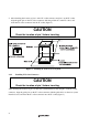
2. After checking the location of pin 1 on the IC socket connector and pin 1 on the IC socket, align the guide pins on the IC socket connector with the guide holes on the IC socket, and insert the IC socket connector into the IC socket (figure 2). CAUTION Check the location of pin 1 before inserting. Figure 2 Installing IC Socket to User System 2.1.2 Installing IC Socket Connector CAUTION Check the location of pin 1 before inserting.
2.1.3 Fastening IC Socket Connector CAUTION 1. Use a hexagonal wrench (φ 1.5 mm). 2. Stop tightening when the force required to turn the screw becomes significantly greater than that needed when first tightening. If a screw is tightened too much, the screw head may break or an IC socket contact error may be caused by a crack in the IC socket solder. 3. If the emulator does not operate correctly, cracks might have occurred in the solder.
2.2 Exchanging the Spacer of the EV-Chip Board While the user system interface board is connected to the user system, force must not applied to the user system. Exchange the spacer (2.6MP x 10 mm) of the EV-chip board with another spacer (2.6MP x 25 mm) provided for the user system interface board. EV-chip board Spacer (2.
2.3 Connecting User System Interface Board to EV-Chip Board WARNING Observe the precautions listed below. Failure to do so will result in a FIRE HAZARD and will damage the user system and the emulator product or will result in PERSONAL INJURY. The USER PROGRAM will be LOST. 1. Always switch OFF the user system and the emulator product before the USER SYSTEM INTERFACE BOARD is connected to or removed from any part. Before connecting, make sure that pin 1 on both sides are correctly aligned. 2.
EV-chip board Connector No. EV-Chip Board Connector No. Board Connector No.
2.4 Recommended Dimensions for User System Mount Pad (Footprint) Figure 6 shows the recommended dimensions for the mount pad (footprint) for the user system with an IC socket for an FP-256H package (TQPACK256RD: manufactured by Tokyo Eletech Corporation). Note that the dimensions in figure 6 are somewhat different from those of the actual chip's mount pad. 30.20 min 26.20 max 0.50 x 51 = 25.50 ± 0.1 42.2 min 38.2 max + 0.1 - 0.05 0.5 x 75 = 37.50 ± 0.1 0.25 0.50 ± 0.05 0.50 ± 0.
2.5 Dimensions for EV-Chip Board and User System Interface Board The dimensions for the EV-chip board and the user system interface board are shown in figure 7. 120.0 8.0 100.0 5.0 5.0 Spacer EV-chip board 100.0 84.0 16.0 8.0 50.0 65.0 34.5 69.0 84.5 5.0 70.0 User system interface board Unit: mm Tolerance: ±0.
2.6 Resulting Dimensions after Connecting User System Interface Board The resulting dimensions, after connecting the user system interface board to the user system, are shown in figure 8. IC socket connector (Tokyo Eletech Corporation TQSOCKET256RDP) 14.5 34.2 59.5 EV-chip board 65.0 IC socket (Tokyo Eletech Corporation TQPACK256RD) User system Spacer (φ6.0) 45.0 45.0 65.0 Unit: mm Tolerance: ±1.
Section 3 Verifying Operation 1. Turn on the emulator according to the procedures described in the SH7058 E6000H Emulator User's Manual (HS7058EPH60HE). 2. Verify the user system interface cable connections by checking the pin states with the CHECK command (emulator command) and checking the bus states with the FILL command (emulator command). If an error is detected, recheck the soldered IC socket and the location of pin 1. 3.
To use the crystal oscillator mounted on the EV-chip board Install a crystal oscillator into the crystal oscillator terminals on the EV-chip board.
Section 4 Notice 1. The MCU cannot be installed directly into the IC socket provided for connecting this user system interface board. 2. Before connecting any parts or cables, make sure that pin 1 on the both sides are correctly aligned. 3. Do not apply excessive force to the user system interface board while it is connected to the user system. 4. The dimensions of the recommended mount pad for the IC socket for this user system interface board are different from those of the MCU. 5.
SH7058 Group FP-256H User System Interface board HS7058ECF61H User's Manual Publication Date: Rev.6.00, January 29, 2004 Published by: Sales Strategic Planning Div. Renesas Technology Corp. Edited by: Technical Documentation & Information Department Renesas Kodaira Semiconductor Co., Ltd. 2004 Renesas Technology Corp. All rights reserved. Printed in Japan.
SH7058 Group FP-256H User System Interface Board HS7058ECF61H User’s Manual 1753, Shimonumabe, Nakahara-ku, Kawasaki-shi, Kanagawa 211-8668 Japan REJ10B0089-0600H