H8S/H8SX Series Direct Drive LCD Design Guide Version 2.6 User’s Manual Direct Drive Solution Rev. 2.60 September, 2009 Renesas Technology America america.renesas.
Direct Drive LCD Design Guide Index 1. INTRODUCTION................................................................................................................................................ 3 1.1 DIRECT DRIVE LCD OVERVIEW ...................................................................................................................... 3 1.1.1 Philosophy ...................................................................................................................................3 1.1.
Direct Drive LCD Design Guide 4. LCD API DEFINITION..................................................................................................................................... 15 4.1.1 4.1.2 4.1.3 4.1.4 4.1.5 4.1.6 4.1.7 4.1.8 4.1.9 4.1.10 Standard Redefines ....................................................................................................................15 LCD API Data Types .......................................................................................................
Direct Drive LCD Design Guide 1. Introduction This document provides technical information of how to configure the LCD panel parameters required by Renesas LCD Direct Driver according to the LCD panel datasheet published by the manufacturers. This document will also describe all the APIs (Application Programming Interface) in the LCD Direct Driver and their usages. An overview of the system hardware is also provided 1.
Direct Drive LCD Design Guide 2. Driver Configuration The LCD Direct Driver is configured through the setting of macro definitions. These macros are illustrated in the sample code. The following table briefly describes the location of each of these macros and their location in LCD Direct Drive demonstration code. For examples of each macro usage, refer to the demonstration code. 2.
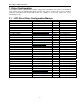
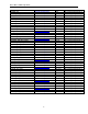
Direct Drive LCD Design Guide Macro Name FRAME_CS FRAME_BUS_CYCLES CAS_LATENCY SDRAM_PAGE_SIZE VSYNC_PORT VSYNC_PIN HSYNC_PORT HSYNC_PIN DOTCLK_PORT DOTCLK_PIN LCD_BACKLIGHT_PORT LCD_BACKLIGHT_PIN EXDMAC_DD EXDMAC_DD_INTC EXDMAC_DD_VECT EXDMAC_DD_REQ_PORT EXDMAC_DD_REQ_PIN DOTCLK_TPU_INTC DOTCLK_TPU_CHANNEL DOTCLK_TPU_PIN DOTCLK_TPU_VECT DOTPER_TPU_CHANNEL DOTPER_TPU_PIN DOTPER_TPU_VECT HPER_TPU_INTC HPER_TPU_CHANNEL HPER_TPU_PIN HPER_TPU_VECT HSYNC_TPU_INTC HSYNC_TPU_CHANNEL HSYNC_TPU_PIN HSYNC_TPU_VECT VS
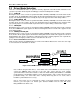
Direct Drive LCD Design Guide 2.2 Frame Buffer Configuration The frame buffer is the external memory area that is used to store the 16bpp image data that will be presented on the LCD screen. The quantity of frame buffers is typically 2 or more. This allows the MCU to be updating one frame wile the ExDMA is transferring the other frame to the LCD panel, this behavior allows for fast transitions and the user does not see operations occurring in the non-displayed buffers.
Direct Drive LCD Design Guide Figure 1. RAM Frame Raster Data Figure 2. PANEL_ROTATE Mode Figure 3.
Direct Drive LCD Design Guide 2.3 Driver Mode Selection There are several different modes of operation currently supported in the Direct Drive LCD driver. The selection of operation mode depends on RAM type selection and LCD panel resolution. 2.3.1 SRAM_DD Defining this macro selects a mode of operation that utilizes SRAM (or PSRAM) as the frame buffer. In this operation mode, the ExDMA ACK signal supplies the Dot Clock during data transfer and the TPU supplies the dot clock during blanking.
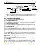
Direct Drive LCD Design Guide Figure 5 H8SX SDRAM in Cluster Mode Note 1: To create the highest LCD Dot Clock frequency on the H8SX requires using cluster mode. In this mode, EDACK is not generated and an equivalent signal must be generated. The above circuit creates the necessary timing. 2.4 Driver Mode Configuration The driver characteristics are configured with the following macros. 2.4.
Direct Drive LCD Design Guide Figure 6 LCD Panel Macro Definitions 2.6 LCD Platform Configuration The LCD Direct Driver is configured to operate with a given hardware platform by setting macro definitions. These values will have to be determined from the schematics on the hardware platform. As an example, the demonstration code can be compared the LCD direct drive hardware schematics. 2.6.
Direct Drive LCD Design Guide 2.6.10 Xxxx_TPU_CHANNEL Enter the channel number for the requested TPU signal. For example if the H8SX DOTCLK is mapped to TPU TIOCB0, enter “0”. 2.6.11 Xxxx_TPU_PIN Enter the pin letter for the requested TPU signal. For example if the H8SX DOTCLK is mapped to TPU TIOCB0, enter “B”.
Direct Drive LCD Design Guide 3. Typical LCD Panel Connections This section illustrates typical connections on an LCD panel and how they are interfaced to the MCU in a Direct Drive configuration. 3.1 LCD panel interface Figure 7 Example Connections for a Kyocera TFT-LCD Panel 3.1.1 Power Supplies Many panels require multiple supplies. Check your panel’s specification to see how many ground and different voltage level connections it requires.
Direct Drive LCD Design Guide entire panel to fill with valid pixels is the maximum refresh rate. Displays in existing media systems usually have refresh rates between 48Hz and 120Hz to avoid visible flicker. HSync, VSync and Dot Clock are all generated using TPU channels of the H8S or H8SX microcontrollers. The TPU allows timer compare actions which synchronize these signals to the ExDMA request line. This ensures that the clocks are generated when valid data is available on the bus. 3.1.
Direct Drive LCD Design Guide 3.2 Hardware Design Below is a block diagram of a LCD system which uses Flash and SRAM for respectively storing and buffering the images to be displayed. The following table describes the TPU channels and pins used for direct drive. Note that the TPU synchronization capability is used to create a common time base between the HDEN, HSYNC and VSYNC pins.
Direct Drive LCD Design Guide 4. LCD API Definition 4.1.1 Standard Redefines These following type have been redefined in order to make the code easier for formatting. typedef typedef typedef typedef typedef typedef 4.1.
Direct Drive LCD Design Guide 4.1.3 LCDInit Direct Driver Initialization. Format LCDErrorType LCDInit(void); Parameters none Return Values 0 if successful, non-zero if failure. Properties Prototyped in file ”DirectLCD.h” Implemented in file “DirectLCD_SBF.c” for H8S family or “DirectLCD_XBCFT.c” for H8SX family. Description This function is used to initialize the hardware necessary for the Direct Drive LCD to execute.
Direct Drive LCD Design Guide 4.1.4 LCDBacklight Direct Driver backlight control. Format void LCDBacklight(int state); Parameters state Requested backlight state 0=off, non-0 = on. Return Values None Properties Prototyped in file ”DirectLCD.h” Implemented in file “DirectLCD_SBF.c” for H8S family or “DirectLCD_XBCFT.c” for H8SX family. Description This function is used to control the state of the LCD backlight.
Direct Drive LCD Design Guide 4.1.5 LCDSetFrameRate Configure the vertical refresh rate of the LCD panel. Format sI16 LCDSetFrameRate(sI16 rate); Parameters rate Requested refresh rate (in Hz) Return Values Negative value indicates rate was not able to be achieved with system configuration. Positive value indicates success, returned value will be the percent of MCU access time available. Properties Prototyped in file ”DirectLCD.h” Implemented in file “DirectLCD_SBF.
Direct Drive LCD Design Guide 4.1.6 LCDGetFrameRate Request the vertical refresh rate of the LCD panel. Format sI16 LCDGetFrameRate(void); Parameters none Return Values Current frame rate in Hz. Properties Prototyped in file ”DirectLCD.h” Implemented in file “DirectLCD_SBF.c” for H8S family or “DirectLCD_XBCFT.c” for H8SX family. Description Request the current vertical refresh rate of the LCD panel.
Direct Drive LCD Design Guide 4.1.7 LCDSetActiveRaster Set memory frame to display. Format uI16 * LCDSetActiveRaster(uI16 frame); Parameters frame Requested frame buffer index. Return Values Pointer to first pixel of frame raster. Properties Prototyped in file ”DirectLCD.h” Implemented in file “DirectLCD_SBF.c” for H8S family or “DirectLCD_XBCFT.c” for H8SX family. Description Request the current vertical refresh rate of the LCD panel.
Direct Drive LCD Design Guide 4.1.8 LCDGetActiveFrame Request which memory frame is currently displayed Format uI16 LCDGetActiveFrame(void); Parameters none Return Values Index of active frame raster. Properties Prototyped in file ”DirectLCD.h” Implemented in file “DirectLCD_SBF.c” for H8S family or “DirectLCD_XBCFT.c” for H8SX family. Description Request which memory frame is currently displayed.
Direct Drive LCD Design Guide 4.1.9 LCDSetRasterOffset Request display location within larger raster image Format sI16 LCDSetRasterOffset(sI16 x, sI16 y); Parameters x X offset in pixels within the raster. y Y offset in pixels within the raster. Return Values 0 on success, non-0 on failure Properties Prototyped in file ”DirectLCD.h” Implemented in file “DirectLCD_SBF.c” for H8S family or “DirectLCD_XBCFT.c” for H8SX family.
Direct Drive LCD Design Guide 4.1.10 LCDSetLineSource Defines the source regions of the active display window. Format sI16 LCDSetLineSource (sI16 Region, sI16 LineCount, uI16 *pSource, sI16 LineStep); Parameters Region Region of display (horizontal strip). Ranging from 0 to MAX_FRAME_REGIONS (defined in DirectLCD_CNF.h). Normally, region 0 starts at the bottom of the screen. However; when V_LINES_INVERT is defined to change line presentation on the screen, region 0 will start at the top of the screen.
Direct Drive LCD Design Guide Website and Support Renesas Technology Website http://www.renesas.com/ Inquiries http://www.renesas.com/inquiry csc@renesas.com Revision Record Description Page Summary — First edition issued Updated — Updated Rev. 1.00 1.10 2.20 Date Jan.28.08 Apr.28.08 Jan.13.09 2.30 Mar.16.09 Updated 2.40 May.11.09 Added LCDSetLineSource to the API. 2.50 June.8.09 Reformatted to new API style. 2.60 Sept.25.2009 Renamed V_LINES_RESOURCE to FRAME_HEIGHT.
Direct Drive LCD Design Guide Notes regarding these materials 1. 2. 3. 4. 5. 6. 7. 8. 9. 10. 11. 12. 13. This document is provided for reference purposes only so that Renesas customers may select the appropriate Renesas products for their use.