
Analog Switch Datasheet

HD74LV1G66A
REJ03D0069-0700 Rev.7.00, Mar 21, 2008
Page 7 of 8
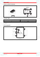
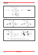
• t
ZH
, t
ZL
/ t
HZ
, t
LZ
V
CC
V
CC
V
CC
GND
GND
Item S1 S2
V
C
V
IN
t
ZH
R =
1 k
L
Ω
C =15 or
50 pF
L
V
OH
V
CC
GND
GND
t
f
t
r
90% 90%
50% 50%
50%
t
ZH
10%10%
V
OUT
V -0.3 V
OH
V +0.3 V
OL
V
C
V
CC
GND
t
ZL
V
CC
GND
t
HZ
V
CC
GND
t
LZ
S1
R =
1 k
L
Ω
S2
t
HZ
50%
V
OL
V
CC
t
ZL
t
LZ
V
OUT
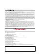
Notes: 1. Input waveform : PRR ≤ 1 MHz, Zo = 50 Ω, t
r
≤ 3 ns, t
f
≤ 3 ns.
2. Waveform - A is for an output with internal conditions such that the output is high
except when disabled by the output control.
3. Waveform - B is for an output with internal conditions such that the output is low
except when disabled by the output control.
4. The output are measured one at a time with one transition per measurement.
Waveform - A
Waveform - B
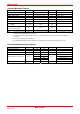
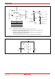
• C
IN/OUT
, C
IN-OUT
V
CC
V
CC
GND
(OFF)
V =GND
C
C
IN/OUT
C
IN/OU
T
C
IN−OUT