
User`s manual


Chapter 5. Block Diagram
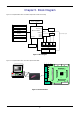
Figure 5-1 is representative of the CPU board components and their connectivity.
Microcontroller
User: 4 LEDS
1Green, 1Orange, 2Red
Application Board
Headers
Potentiometer
Microcontroller Pin
Headers
D-type latch
RESn
RESET pin
BOOT
RES
SWITCHES
IRQ pin
Power Jack Option
SW3SW2
Boot Circuitry
BOOT & BOOTn signals
Power: Green
Boot: Orange
LEDs
Boot mode pins
Debug Header Option
LCD
IRQ pin
IRQ pin
ADC Input
Serial Connector Option
Figure 5-1: Block Diagram
Figure 5-2 is representative of the connections required to the RSK.
Computer
MCU
Optional Expansion Bus
connector
S
W
1
S
W
2
S
W
3
R
E
S
POT
E8
Other
Serial D9
SKT
JA1
JA2
JA3
JA6
JA5
J1 -
Applies to connector
with micriocontroller pin1
J2
J4
J3
Figure 5-2 : RSK Connections
6