
User's Manual


Rev.2.00 Nov 28, 2005 page 330 of 378
REJ09B0124-0200
M16C/6N Group (M16C/6NK, M16C/6NM) 22. Electric Characteristics (T/V-ver.)
Under development
This document is under development and its contents are subject to change.
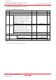
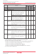
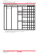
Table 22.48 Recommended Operating Conditions (2)
(1)
Main Clock Input Oscillation No Wait
Flash Memory
VCC = 4.2 to 5.5V
Frequency
(2) (3) (4)
Version
Sub Clock Oscillation Frequency
On-chip Oscillation Frequency
PLL Clock Oscillation Frequency
CPU Operation Clock
VCC = 4.2 to 5.5V
PLL Frequency Synthesizer Stabilization Wait Time
Power Supply Ripple Allowable Frequency (VCC)
Power Supply Ripple Allowable Amplitude Voltage VCC = 5V
Power Supply Ripple Rising/Falling Gradient VCC = 5V
32.768
1
MHz
kHz
MHz
MHz
MHz
ms
kHz
V
V/ms
0
16
0
16
50
20
20
20
10
0.5
0.3
f(XIN)
f(XCIN)
f(Ring)
f(PLL)
f(BCLK)
t
su(PLL)
f(ripple)
VP-P(ripple)
VCC(|∆V/∆T|)
ParameterSymbol
Typ.Min.
Standard
Unit
Max.
NOTES:
1. Referenced to VCC = 4.2 to 5.5V at Topr = –40 to 85°C unless
otherwise specified.
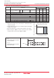
2. Relationship between main clock oscillation frequency and supply
voltage is shown right.
3. Execute program/erase of flash memory by VCC = 5.0 ± 0.5 V.
4. When using over 16MHz, use PLL clock. PLL clock oscillation
frequency which can be used is 16MHz or 20MHz.
0.0
16.0
5.54.2
VCC [V] (main clock: no division)
Main clock input oscillation frequency
(Flash memory version: no wait)
f(XIN) operating maximum frequency [MHz]
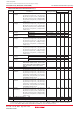
f(ripple)
Power Supply Ripple Allowable
Frequency (VCC)
V
P-P(ripple)
Power Supply Ripple Allowable
Amplitude Voltage
Figure 22.21 Timing of Voltage Fluctuation
f
(ripple)
V
P-P(ripple)
VCC