
User's Manual

Rev.2.00 Nov 28, 2005 page 259 of 378
REJ09B0124-0200
M16C/6N Group (M16C/6NK, M16C/6NM) 20. Programmable I/O Ports
Under development
This document is under development and its contents are subject to change.
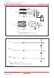
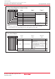
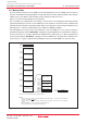
Figure 20.12 Unassigned Pins Handling
NOTES:
1.If the PM07 bit in the PM0 register is set to "1" (BCLK not output), connect this pin to VCC via a resistor. (pulled high).
2.The ports P11 to P14 are only in the 128-pin version. When not using all of the P11 to p14 pins may be left open by setting
the PU37 bit in the PUR3 register to "0" (P11 to P14 unusable), without causing any problem.
3. Not available in T/V-ver..
Microcomputer
In single-chip mode
Port P0 to P14 (Input mode)
(except for P8_5)
(2)
(Input mode)
(Output mode)
NMI
XOUT
AVCC
BYTE
AVSS
VREF
Open
VCC
VCC
VSS
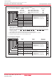
Microcomputer
Port P4_5/CS1
to P4_7/CS3
In memory expansion mode or
in microprocessor mode
(3)
Port P6 to P14 (Input mode)
(except for P8_5)
(2)
(Input mode)
(Output mode)
NMI
BHE
HLDA
ALE
XOUT
BCLK
(
1)
HOLD
RDY
AVCC
AVSS
VREF
Open
VCC
VCC
VCC
VSS
Open
Open