REJ10J0143-0401Z USB Flash Writer User's Manual RENESAS SINGLE-CHIP MICROCOMPUTER M16C FAMILY / 740 FAMILY Rev.4.01 Revision date: Dec 24, 2004 Renesas Solutions Corp. www.renesas.
Keep safety first in your circuit designs! 1. Renesas Technology Corporation puts the maximum effort into making semiconductor products better and more reliable, but there is always the possibility that trouble may occur with them. Trouble with semiconductors may lead to personal injury, fire or property damage.
Microsoft, MS, and MS-DOS are registered trademarks of Microsoft Corporation of the U.S. Windows is trademark of Microsoft Corporation of the U.S. IBM and PC/AT are registered trademarks of International Business Machines Corporation of the U.S. Pentium is a trademark of Intel Corporation of the U.S. Adobe and Acrobat are registered trademarks of Adobe Systems Incorporated. Preface Thank you for purchasing Renesas USB Flash Writer (M3A-0665).
Table of Content Table of Content 1. Contents of Product ......................................................................................................................................... 4 1.1 Contents of product ........................................................................................................................................ 4 1.2 Operating Environment ............................................................................................................................
Table of Content 4.2.Other Functions ............................................................................................................................................48 5. Using the KD ..................................................................................................................................................49 5.1 Using the KD.................................................................................................................................................
Table of Content 6.7 A communication error occurred when debugging the program. What is the cause of this problem? ......74 6.8 A message "Source file cannot be found" was output. What should I do?.................................................75 6.9 Is peripheral I/O operating during a break? .................................................................................................75 6.10 Can coveragefunction be used in KD?..........................................................................
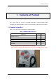
1 Contents of Product 1. Contents of Product This section shows the contents of theUSB Flash Writer’s product package. When unpacking your USB Flash Writer, check to see that all products listed below are included. 1.1 Contents of product Table 1-1 lists the products included in the USB Flash Writer. Table 1-1 USB Flash Writer Product List Product List Quantity Remark USB Monitor Board 1pc USB Cable (Used for the connection with the Host Computer.) 1pc Flat Cable 1pc Pin Header (HIF3FC-10P-2.
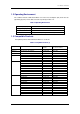
1 Contents of Product 1.2 Operating Environment The software includes USB Flash Writer run on the Host Computer (PC) under the OS (Operating System) version that are listed respectively in Table 1-2. Table 1-2 Operating Environment Host Computer (PC) IBM PC/AT series or its compatible OS (Operating System) Microsoft Windows 98SE/ME/2000/XP CPU Pentium II 233MHz or newer recommended Memory 8 Mbyte or more (16 Mbyte recommended) 1.
1 Contents of Product Table 1-4 Compatible Products (2) Group MCU Product Name Corresponding MCU Product Name Software to select in Software M16C/24 M30245FCGP FoUSB, KD30 M30245FC M16C/62A(M) M30620FCAFP/GP, M30621FCAGP FoUSB, KD30 M30620FCA FoUSB, KD30 M30624FGA M30622F8PFP/GP FoUSB, KD30 M30622F8P M30623F8PGP FoUSB, KD30 M30623F8P M30620FCPFP/GP FoUSB, KD30 M30620FCP M30621FCPGP FoUSB, KD30 M30621FCP M30624FGPFP/GP FoUSB, KD30 M30624FGP M30625FGPGP FoUSB, KD30 M30625FGP
1 Contents of Product 1.4 Board Specification Table 1-5 shows the USB Monitor Board Specification. When saving these products, put them into the conductive bag.
1 Contents of Product 1.5 CD-ROM The CD-ROM contains software products necessary for developing programs and electronic manuals as well. Here follow the contents of the CD-ROM. CD-ROM: Rev.2.10 or later \root |--- Readme_e.txt |--- Readme_j.
2 Product Specifications 2. Product Specifications 2.1 FoUSB (Flash-over-USB) FoUSB is the software that allows you to operate on M16C, M32C, R8C or 740 microcomputers with built-in flash memory from a Windows version host computer (Windows 98SE or later). 2.2 KD30/KD3083 The KD included with the package is the debug software that runs on a Windows version host computer.
2 Product Specifications Table 2-2 PD308F and KD3083 comparison No. Item PD308F KD3083 1 Software break function 64 points 4 points to 8 points (Note) 2 Hardware break function 6 points not included 3 RAM monitor function included included 4 Real time trace included not included 5 Time measurement function included not included 6 Script function included included Note: Software break numbers are dependent on the address match circuit numbers are built-in MCU.
3 Installing 3. Installing 3.1 Before installing Do not connect the USB Cable which belongs to this product to the Host computer (PC) before installing. 3.2 Preparation before installing Be sure to confirm the following point before performing installation of a tool (GUI) and a driver. (1) The CD-ROM includes files required for the FoUSB (Flash-over-USB) installation. Copy all files to any folder in your PC before installation.
3 Installing 3.3 FoUSB (Flash-over-USB) installing 3.3.1 Method of Installation 1) To install FoUSB, double-click “FoUSB_V.*.**.exe” on the folder into which you’ve copied FoUSB files from the CD-ROM. 2) Select the language of installer. 3) Click the button. 4) Only when you agree, click the button.
3 Installing 5) Choose the component which you want to install and click the button. NOTICE: Explanation of install component (a) Shortcut on Desktop The shortcut of a FoUSB (Flash-over-USB) execution file is created on a desktop. (b) Install USB Drivers FoUSB installer installs a USB Driver in the correct location of Windows system automatically. We recommend choosing this component in all operating systems.
3 Installing 6) Choose the install location of FoUSB and click the button. The default install location of FoUSB is “C:\MTOOL\FOUSB”. 7) The following figure is displayed when the install component “Install USB Drivers” is choosen. Click the button. Next, warning is displayed. Please check that USB Monitor Board is not connected to your host computer (PC), and click the button.
3 Installing 8) When an operating system is Windows XP, notes screen is displayed. Click the button. Then the software install screen is displayed two times (for USBMON Driver and FoUSB Driver), click the button twice (Note). Note: Microsoft has advocated authentication of the USB drivers to the USB vendors in the Microsoft® Windows® XP and Windows®-based operating systems released after Microsoft® Windows® XP.
3 Installing 10) The following figure is displayed when installation of USB Driver is completed. Click the button. 11) When the install component “Update KD30 Files” is chosen, FoUSB installer seaches KD30 with a firmware older than the firmware of FoUSB. The following figure will be displayed if KD30 is detected. If you want to update a firmware, click the button. When button is clicked, the firmware of KD30 is not updated.
3 Installing 12) Finally, click the button. 13) Now you’ve finished installing the FoUSB (Flash-over-USB). 3.3.2 Method of Uninstallation To uninstall the FoUSB (Flash-over-USB) you've installed, choose Settings -- Control Panel from the Start menu, and then click “Add/Remove Programs”. Select "Flash-over-USB V.*.** " from the program list and click the button. An uninstall window will appear, with the Flash-over-USB V.*.** compiler uninsalled.
3 Installing 3.4 Recognition of USB Monitor Board From installer version “V.2.04”, the FoUSB installer has an automatic USB Driver install function (Refer to [3.3 FoUSB (Flash-over-USB) installing].). This section explains recognition of USB Monitor Board when confirming this function and installing FoUSB. When this function is not confirmed, please perform installation of a USB Driver, and recognition of USB Monitor Board with reference to [7.
3 Installing 3) When an operating system is WIndows 98SE/ME/2000, Windows system detect USB Driver automatically and recognizes USB Monitor Board. Recognition of USB Monitor Board for USBMON Driver is completion. 4) When an operating system is Windows XP, Windows system displays the Found New Hardware Wizard screen. Then, choose “Install the software automatically” and click the button. 5) Next, the Hardware Installation screen is displayed, click the button (Note).
3 Installing 6) Click the button. Windows system recognizes USB Monitor Board (for USBMON Driver). Recognition of USB Monitor Board for USBMON Driver is completion. 3.4.2 Recognition of USB Monitor Board 2 (for FoUSB Driver) 1) Remove the cover of USB Monitor Board and make a USB Monitor Board (Board) the following setup, before connecting USB Monitor Board to your host computer (PC). If a setup is completed, attach a cover in a USB Monitor Board (Board).
3 Installing 2) Connect the USB Monitor Board included with the package to the USB port of PC. The Power indicator (D1: Power) of USB Monitor Board lights. Figure 3-4 USB Monitor Board connectivity 3) When an operating system is WIndows 98SE/ME/2000, Windows system detect USB Driver automatically and recognizes USB Monitor Board. Recognition of USB Monitor Board for USBMON Driver is completion. Please skip to 7).
3 Installing 5) Next, the Hardware Installation screen is displayed, click the button (Note). Note: Microsoft has advocated authentication of the USB drivers to the USB vendors in the Microsoft® Windows® XP and Windows®-based operating systems released after Microsoft® Windows® XP. This is aimed at elimination of illegal drivers and improvement of host computer (PC). Renesas USB Drivers are not authenticated by Microsoft, but we provide them baased on the sufficient examination.
3 Installing 3.4.3 Other Notes Caution: The “USB Drivers” folder below is stored. Driver Name USBMON Driver Description Related Files USBMON driver is a driver for using usbmon.sys FoUSB (Flash-over-USB) and KD (KD30, usbmon.inf KD3083) FoUSB Driver FoUSB driver is a driver for using USB fousb.sys MCU (M367641F8) of USB Monitor fousb.inf Board in Boot mode. (Note) (Note) The Boot mode of USB MCU is used only for the use shown below.
3 Installing 3.5 KD30/KD3083 intalling 3.5.1 Installing 1) Installing the Remote Debugger Double-click installer file on the CD-ROM (\KD\KD30) for KD30. In KD3083, the installer file is included in \KD\KD3083. 2) A flow of installation procedures is shown in the pages that follow. (a) Click the button. (b) Click the button.
3 Installing (d) Click the button. A default install location is “C:\MTOOL”. If an install location is changed, please click the button and determine an install location. (e) Click the button. (f) Click the button. 3) Now you've finished installing the KD30. Note: The installation of KD3083 is the same.
3 Installing 3.5.2 Uninstalling the Remote Debugger To uninstall, choose Settings -- Control Panel from the Start menu, and then click the “Add/Remove Programs”. Select KD from the program list and click the button. An uninstall window will appear, with the integrated development environment uninsalled. The uninstallation of KD3083 is the same, too.
4 Using the FoUSB 4. Using the FoUSB 4.1 Using the FoUSB (Flash-over-USB) 4.1.1 Before Starting the FoUSB 1) Check to see that the FoUSB is installed in your host computer (PC). 2) Check to see that PC, USB Cable, USB Monitor Board, Flat Cable and Target Board are firmly connected. (See Figure 4-1) 3. USB Monitor Board 1. USB Cable 4. Flat Cable 2. Target Board 5.
4 Using the FoUSB 3) Connection Method It specifies as a premise that MCU is carried on the Target Board. (1) Connection order when using the USB bus-powered. Connect in order of 2-4-3-1-host computer (PC). (2) Separation order after using the USB bus-powered. Connect in order of PC-1-3-4-2. (3) Connection order when using external power supply. Set a power source supply selector to the TARGET side. Connect in order of PC-1-3-4-2 and finally supply power from outside.
4 Using the FoUSB (2) When using 3.3 V The power for the Target MCU is not supplied from the USB Monitor Board and must therefore be supplied from the Target Board. In this case, set the power source supply selector on the USB Monitor Board to the TARGET side as shown in Figure 4-3. When using 3.3 V, set the switch to the TARGET side.
4 Using the FoUSB 4.1.2 FoUSB starts 1) From the Start menu, choose Programs -- RENESAS-TOOLS – Flash-over-USB V.*.** -- FoUSB Programmer to start the FoUSB. When the FoUSB starts, the FoUSB main window shown in Figure 4-4 appears. i) Main button 1 iii) MCU select button iv) Monitor information v) Detail button ii) Update button vi) Main button 2 Figure 4-4 FoUSB main window 2) Guide to understanding the display of the main screen No.
4 Using the FoUSB 4.1.3 Details of Main Button 1 1) “OPEN” button This button reads the downloading (programming) file to the Target MCU. (1) Click the “OPEN” button, and the screen shown in Figure 4-5 will appear, allowing you to choose the file to download into the Target MCU. The type of file that can be downloaded is HEX or Motorola. After selecting the file to download, click the button. Figure 4-5 Open screen (2) The ID code is automatically read in. Click the button.
4 Using the FoUSB 2) “READ” button This button performs to verify data written in the Target MCU and the file read by “OPEN”. Also, performs to read out data written in the Target MCU. (1) Clik the “READ” button, Figure 4-7 screen will appear. Figure 4-7 Flash Memory Read screen-1 (2) For Verify, click the button and the file downloaded by “OPEN” and data written in the Target MCU will be verified. If the verified result matches, Figure 4-8 will appear. Click the button.
4 Using the FoUSB (3) For “Read Area”, specify the range of data to read in hexadecimal. By default, the data opens in a custom window. Click the button, and the downloaded data will be displayed, but not saved. If you wish, select the check box in the Options section, and ASCII code will be added to the downloaded data.
4 Using the FoUSB (4) To change the custom window used for displaying data to an editor, select the . By default, data is displayed in Notepad. To change Notepad to any editor, click the button. (See Figure 4-11) Figure 4-11 Flash Memory Read screen-3 (5) To save the read data, select the and click the button. (See Figure 4-12) Then enter a name for the file.
4 Using the FoUSB Figure 4-13 Save screen 3) “ERASE” button This button erases the Flash ROM in the Target MCU. (1) When you click the “ERASE” button, the screen changes to one of the following two depending on whether you’ve downloaded data using “OPEN”. (2) Before downloading You can choose to erase all blocks (Select All) or erase evry one block. When you select a block to erase, the check box by block is indicated with a check mark and the block is displayed in color.
4 Using the FoUSB (3) After downloading The system reads information from the downloaded data to determine which block to erase and marks the corresponding check box with a check mark and displays the block in color. Click the button, and the block will be erased. You can erase all blocks collectively or one block at a time. (See Figure 4-15) Figure 4-15 Erase Flash-2 4) “UNLOCK” button This button sends the ID code to the locked Target MCU, and unlock the Target MCU.
4 Using the FoUSB When you click the “UNLOCK” button, the system checks ID code. The ID code check has automatic setting and manual setting. (1) Automatic setting Automatic setting checks in the following condition in ID code of “All FFh” and “All 00h”. >> When FoUSB is started. >> When a firmware is changed during FoUSB use. This condition shows FoUSB restart. If the ID code consists “All 00h”, Figure 4-16 will be displayed, and the Target MCU is unlocked.
4 Using the FoUSB (2) Manual setting If you click the “UNLOCK” button, Figure 4-17 will be displayed. Enter the ID code and click the button. When the ID code written in the Target MCU matches with the input ID code and Figure 4-18 will be displayed. When the ID code does not match, Figure 4-19 will be displayed (Target MCU is locked) and enter the correct ID code. Figure 4-17 ID code dialog Figure 4-18 ID code match Figure 4-19 ID code not match The setting method of the ID code is the following.
4 Using the FoUSB Example of File input In this example, the ID code of “01 02 03 04 05 06 07” is programmed in the Target MCU. First, click the “OPEN” button and open the HEX file or Motorola file which has an ID code. Click the button on the ID code screen which FoUSB displays. The Motorola file with the ID code of “01 02 03 04 05 06 07” is open in this example. Next, click the “UNLOCK” button. The screen into which the ID code of the read file was input is displayed.
4 Using the FoUSB NOTICE: ID code address of MCU Series M16C/10 M16C/20 M16C/Tiny M16C/60 M16C/80 M32C/80 R8C/Tiny 740 38000 ID code address ID1: 0FFFDFh ID2: 0FFFE3h ID3: 0FFFEBh ID4: 0FFFEFh ID5: 0FFFF3h ID6: 0FFFF7h ID7: 0FFFFBh ID1: 0FFFFDFh ID2: 0FFFFE3h ID3: 0FFFFEBh ID4: 0FFFFEFh ID5: 0FFFFF3h ID6: 0FFFFF7h ID7: 0FFFFFBh ID1: 0FFDFh ID2: 0FFE3h ID3: 0FFEBh ID4: 0FFEFh ID5: 0FFF3h ID6: 0FFF7h ID7: 0FFFBh ID1: 0FFD4h ID2: 0FFD5h ID3: 0FFD6h ID4: 0FFD7h ID5: 0FFD8h ID6: 0FFD9h ID7: 0FFDAh The ID c
4 Using the FoUSB 5) “PROGRAM” button This button performs programming to the Target MCU. (1) Click the “PROGRAM” button, and the screen shown in Figure 4-20 will appear. Figure 4-20 Program Flash screen (2) In the Choose an Options section, select either “Erase -> Program -> Verify” or “Program Only”. (a) Erase -> Program -> Verify (without lock bit function) When you select this option, processing is performed in order of Erase, Program and Verify.
4 Using the FoUSB (3) Erasing Options is useful when you select “Erase -> Program -> Verify” for Choose An Options, allowing you to select the method for erasing flash memory blocks. (a) Erase All Blocks All flash blocks are erased (b) Erase Only Needed Block Only the corresponding flash block is erased. 4.1.4 Details of the Update Button Use the “Update” button when you want to upgrade the version of FoUSB.
4 Using the FoUSB 4.1.5 Details of the Select MCU Button 1) The following MCUs can be selected in FoUSB.
4 Using the FoUSB 2) When pressing the "Select MCU" button, the screen shown in Figure 4-21 is displayed. Select the Target MCU in this screen. First, select the category of the Target MCU to be used form the MCU Category Column (M16C/26 Group is selected from M16C/Tiny Series in Figure 4-21). Next, select the Target MCU to be used from the MCU Select Column. If the MCU which is indicated by highlight is duble-click or button is clicked, the confirmation screen will be displayed.
4 Using the FoUSB 5) When the system has finished download the firmware, the screen shown in Figure 4-24 is displayed. Click the button. Figure 4-24 Completion screen NOTICE: The cautions about firmware download in 3.3V operation In 3.3V operation, firmware download to USB Monitor Board cannot be performed. The following error screen will be displayed if the firmware is downloaded to USB Monitor Board in 3.3V operation.
4 Using the FoUSB c) Start FoUSB. At this time, although the following error screen is displayed, ignore the error and click the button. Figure 4-25 Error screen d) Click the “Select MCU” button and download the firmware to the USB Monitor Board. (Refer to 2) to 5) of this section for details) e) When the download of the firmware is completed, Figure 4-25 will be displayed again. Ignore the error and click the button. Finish FoUSB.
4 Using the FoUSB 4.1.6 Monitor Information 1) Monitor Firmware The version of the firmware currently written in the USB Monitor Board is indicated here. 2) MMI Loaded The name of the firmware currently written in the USB Monitor Board is indicated here. 3) Serial Boot Code The boot version written in the MCU is indicated here. 4.1.7 Detailed File Information 1) DETAILS button Shows details of the downloaded data (program size, ID code, blocks and sections used).
4 Using the FoUSB (1) Contents of Options Debug Mode: Whether debug mode is available (Unusable) Show splash screen: Whether FoUSB sound is available Ignore FoUSB Devices: Whether FoUSB devices are included (Unusable) Ignore Monitor Devices: Whether USB monitor is included (Unusable) Auto Unlock: Whether or not to automatically set ID code Multi-Programming Mode: Whether Multi-Programming Mode is available (Unusable) Language: Language select (2) Automated Programming This function currently cannot be used
5 Using the KD 5. Using the KD 5.1 Using the KD 5.1.1 Before Starting the KD 1) Corresponding MCU become only R8C/Tiny, M16C/10, M16C/20, M16C/Tiny, M16C/60 series, M16C/80 and M32C/80 series. 2) Check to see that the KD is installed in your host computer (PC). 3) Check to see that PC, USB Cable, USB Monitor Board, Flat Cable and Target Board are firmly connected.
5 Using the KD 5.1.2 Starting the KD 1) From the Start menu, choose Programs -- RENESAS-TOOLS – KD30 V.*.** Release* -- KD30 to start the KD. When the KD starts, the screen shown in Figure 5-2 appears. If the screen appears, click the button and choose MCU File. Note: In the case of M16C/80 and M32C/80, start KD3083. Figure 5-2 Init screen-1 2) Next, the Select MCU File screen on Figure 5-3 will be displayed.
5 Using the KD 3) The Init screen of the Figure 5-4 opens when it is done after a MCU File is chosen. Choose “USB” as the communication interface and click the button. Figure 5-4 Init screen-2 NOTICE: Precautions on KD3083 Emulation Memory The address allocated to the Emulation Memory cannot be debugged in the KD3083. Therefore, allocate the Emulation Memory to the address which is not used in debug. The address in the Emulation Memory can be modified by the bank address (default vale: F0).
5 Using the KD (a) At first an example to which the Emulation Memory overlaps the User Program is shown. In this example, the User Program is allocated from F00000h and the Emulation Memory is allocated from F00000h (using default value F0 of bank address). Therefore, the Emulation Memory overlaps the User Program and contes of the User program and asseble codes are not matched. Bank Address F00000h Emulation Memory 64KB F10000h User Area The Emulation Memory overlaps the user program.
5 Using the KD (b) Then an example to which the Emulation Memory does not overlap the User Program is shown. In this example, the User Program is allocated from F00000h and the Emulation Memory is allocated from E00000h (set E0 to the bank address). Since the Emulation Memory does not overlap the User Program, contents of the User Program and assemble codes are matched. Bank Address E00000h Emulation Memory E10000h 64KB The Emulation Memory does not overlap the user program.
5 Using the KD 4) This KD Main screen appears when the KD was able to communicate normally at startup. D. Reset button C. Stop button B. Step button A.
5 Using the KD 5.1.3 Program Download 1) Download a program by "File -- Download" in KD Main screen. Please note that "SKPTest.x30" is not included in this product. Figure 5-7 Program Download 2) When completing the download, a program which is downloaded into "Program window" is indicated (See Figure 5-8).
5 Using the KD 5.1.4 Program Execution When completing download, click the "Go" button on the KD Main screen to execute a program. After this, the program is executed. Figure 5-9 Program Execution 5.1.5 Program Stop Click the "Stop" button on the KD Main screen (Figure 5-6, C) to stop the program which is already executed after this, the program is stopped the KD Main screen is as Figure 5-8. 5.1.
5 Using the KD 5.1.7 Software Break Method When executing the software break, the software break can be set as the place which has "-" in "BRK" in Program Window screen. The KD Main screen is as Figure 5-10. Software break point Figure 5-10 Software Break 5.1.8 Reset Execution User Program is in the same status as immediately after download. Click the "Reset" button (Figure 5-6, D) on the KD Main screen. 5.1.9 KD Completion 1) Before completing a KD, stop the User Program.
5 Using the KD 5.1.10 If a Communication Error Occurs If a communication error occurs, the error screen shown in Figure 5-11 appears. In that case, click the “OK” button and check the following two points. When you finished checking, restart the KD. Check1: Is the power source supply selector on the USB Monitor Board set to USB side? Check2: Are the USB Cable and Flat Cable are firmly inserted into position? Figure 5-11 Communication Error screen 5.1.
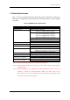
5 Using the KD 5.2 KD Limitations 5.2.1 Limitations on Special Page Vector A Monitor Program uses several Special Page Vectors. Therefore, the Special page Vector which can be used in the User Program is limited as Special Page Vector Number shown in the following table. When updating the version of the Monitor Program (or Firmware), the Special Page Vector which can be used in the User Program may be modified.
5 Using the KD 5.2.2 A limitation item about the C language When using Renesas C compiler. It is necessary to change a start up file (ncrt0.a30 and sect30.inc). (1) The change point of “ncrt0.a30” (a) Initialize standard I/O The UARTi setting is modified in the I/O initialization treatment. Therefore, to ensure that the I/O initialization treatment is not called up, comment it out.
5 Using the KD 5.2.3 Limitations on Memory Extension When using memory extension, make sure the power source supply selector on the USB Monitor Board is set to the TARGET side so that the power for the Target MCU will be supplied from the Target Board. Memory extension cannot be used when the selector is set to the USB side. 5.2.4 Precautions on Internal Reserved Area Expansion Bit a.
5 Using the KD 5.2.5 Limitations on Stop and Wait Modes To use stop or wait modes in the User Program, start the KD in free-run mode. If you want to debug, close the RAM, C Watch and ASM Watch Windows before actually debugging. Furthermore, set a breakpoint or take other necessary measures when getting out of stop or wait mode in order to ensure that no window operations will be performed until the program stops at the breakpoint. 5.2.
5 Using the KD 5.3 Memory Map Limitations Table 5-2 and Table 5-3 list the ROM/RAM areas which the monitor program uses. Figure 5-12 shows the memory map.
5 Using the KD Table 5-3 ROM/RAM areas (2) Group M16C/6N M16C/80 M32C/83 M32C/84 M32C/85 M32C/86 M32C/87 R8C/10 R8C/11 R8C/12 R8C/13 MCU M306N4FC M306N5FC M306N4FG M306NBFC M306NAFG M30800FC M30803FG M30833FJ M30835FJ M30845FJ M30855FW M30855FH M30852FJ M30865FJ M3087BFL R5F21102 Note1 R5F21103 Note1 R5F21104 R5F21112 Note2 R5F21113 Note2 R5F21114 R5F21122 Note3 R5F21123 Note3 R5F21124 R5F21132 Note4 R5F21133 Note4 R5F21134 ROM/RAM 128K/5K 128K/5K 256K/10K 128K/5K 256K/10K 128K/10K 256K/20K 512K/31K
5 Using the KD 000000h 00000h 00000h SFR 00400h SFR User RAM Area XXXXXh YYYYYh Monitor RAM Area SFR 00400h 000400h User RAM Area XXXXXh YYYYYh Monitor RAM Area User RAM Area YYYYYh 0C000h Monitor Area ZZZZZh ZZZZZh ZZZZZh Flash Memory Flash Memory Flash Memory FF900h FFF900h Monitor Area FFEFFh Monitor Area 0FEFFh FFFEFFh User Fixed Vector Area FFFFFh User Fixed Vector Area 0FFFFh FFFFFFh [M16C Series] User Fixed Vector Area [M16C/80, M32C/80 Series] Figure 5-12 Mmemory map 65
5 Using the KD 5.4 Peripheral Function Related Limitations 1) UART pins (TxDi, RxDi) The UARTi transmit and receive interrupts are used for communication between the USB Monitor Board and host computer (PC). Make sure that UARTi is not used in the User Program. Do not connect the UART pins with other pins.
5 Using the KD 5.5.1 Communication Function with FoUSB The clock synchronous serial I/O is used for FoUSB and the monitor program communication. When the data is received, the DBC interrupt generates and the monitor program is executed. The DBC interrupt is not influenced of I flag. (The receive interrupt is used for some models because there is no DBC interrupt. In this case, the DBC interrupt is influenced of I flag). The monitor program analyzes the received data and executes each command. 5.5.
5 Using the KD 5) RAM monitor When using RAM monitor, a User Program execution is stopped temporarily. 6) Register reference When using register reference, a User Program execution is stopped temporarily and the data of CPU register and SFR is transferred. 7) User Program stop A User Program stops, a monitor program operates and it waits for next command. 5.5.
6 Troubleshooting 6. Troubleshooting 6.1 FoUSB cannot communicate with the Target MCU Why? It is possible that the firmware written in the USB Monitor Board has gone wild. In such a case, temporarily remove the USB Cable and insert it back into position. 6.2 The MCU cannot enter standerd serial I/O why? 1) Check to see that the Busy signal is connected to the writer’s connector accurately. 2) Check to see that the Reset signal is pulled up (5K) on a board. 6.
6 Troubleshooting Figure 6-1 FoUSB main window lights only Figure 6-2 USB Monitor Board (Board) In such a case, it is necessary to download firmware compulsorily to USB MCU. Please perform compulsive download of firmware to USB MCU according to the procedure shown in the following page.
6 Troubleshooting 6.4.1 Compulsive download procedure of firmware 1) Remove the cover of USB Monitor Board and make a USB Monitor Board (Board) the following setup. Shorted USB side 2) Connect the USB Monitor Board (Board) with your host computer (PC). 3) Start FoUSB (Flash-over-USB) and click the “Load MMI” button on a GUI window.
6 Troubleshooting 4) On the Chip Selection screen, select your MCU and download a firmware to the USB MCU. (1) Select your MCU (2) Click here 5) If download of firmware is completed to USB MCU, since the completion screen of download will be displayed, click the button. 6) End FoUSB and separate a USB Monitor Board (Board) from your host computer (PC). 7) Make Open JP1 (MCU Mode Pin) of the USB Monitor Board (Board).
6 Troubleshooting 8) Connect USB Monitor Board (Board) with your host computer (PC). 9) Since firmware has downloaded normally if a Power indicator (D4: Status) is lighting and the Status indicator is blinking as shown in the following figure, FoUSB and KD (KD30, KD3083) can be used. blinking lighting 10) Separete USB Monitor Board (Board) from PC and attach a cover in the USB Monitor Board (Board). 11) Now you've finished compulsive downloading the firmware.
6 Troubleshooting 6.5 Can FoUSB information be transmitted to KD? A written program using FoUSB cannot be debugged with KD. It is necessary to download a program on KD again when executing debug using KD. Therefore, written program information in flash area is not transmitted to KD30 (KD3083). 6.6 A communication error occurs when the KD starts. What is the cause of this problem? If a communication error occurs when the KD starts, check the following.
6 Troubleshooting 3) If a communication error occurs frequently when debugging your program, check the following: When using an interrupt program in which multiple interrupts (interrupt from within another interrupt) are not enabled... -> If the interrupt program takes more than 260 µs of processing time, set the I flag to 1 at the beginning of the interrupt program. 6.8 A message "Source file cannot be found" was output.
6 Troubleshooting 6.13 Debug operation has not worked well Isn’t the resource of a Monitor Program used? When using the resource of the Monitor Program in debug, a communication error or an unexpected operation may occur. Therefore, note that the resource of the Monitor Program should not be used. a. Peripheral (Serial I/O) The BUSY, SCLK, TxD and RxD pins are used for communications between the Target MCU and KD30/KD3083. Do not connect a user I/O to these pins. Related section: [5.
6 Troubleshooting e. Interrupt Interrupts shown below are the resources of the Monitor Program. Do not use these interrupts. Also, some microcomputers do not support the DBC interrupt (Note). In microcomputers which do not support the DBC interrupt (ex.: M16C/62A group), the UARTi receive interrupt is used.
6 Troubleshooting 6.14 Message List The following lists the messages output by FoUSB. Normal message Your device has been automatically unlocked with the ID code. The correct firmware already loaded on the USB Monitor Board. Do you want to reprogram anyway Programming in new firmware image Download successful!! Verify passed A file has been loaded that will create an ID code of 00 00 00 00 00 00 00 on the current attached device.
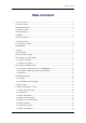
7 Appendix 7. Appendix 7.1 USB Monitor Board 7.1.1 Board Specifications Figure 7-1 list Board specifications of USB Monitor Board.
7 Appendix 7.1.2 Pin Assignments As an example of M16C/62A group, Pin assignments of the 10-pin connector (for Flat Cable) are shown in Figure 7-2. Pin No. 1 Pin No. 1 2 3 4 5 6 1 2 3 4 5 6 7 8 9 10 7 9 8 10 10-Pin connector Port P6_4 P6_5 P6_6 P5_0 P5_5 P6_7 Signal Vcc BUSY SCLK RxD CE EPM GND RESET CNVss TxD Figure 7-2 An example of 10-Pin connector pin assignment 7.1.
7 Appendix Example Connection for M16C/62A(M), 6N(M306NAFG, M306NBFC only), M3062GF8N, 80, 24 Vcc 0.1uF Vcc USB Monitor Board BUSY SCLK CE GND FLAT Cable Connection CNVss 1 2 3 4 5 6 7 8 9 10 0.1uF RxD EPM RESET Vss P64/CTS1/RTS1/CTS0/CLKS1 30pF 10-Pin Connector assign P66/RxD1 Pin No 1 Port Signal P55/HOLD 2 3 4 p6_4 p6_5 p6_6 Vcc BUSY P67/TxD1 5 6 7 P5_0 P5_5 10 p6_7 AVcc AVss Connector Type HIF3FC-10PA-2.
7 Appendix Example Connection for M16C/26, 26A, 28, 29 [1] Note: It is necessary to connect the CE pin or the EPM (RP) pin and the P1_6 pin. The CE pin is connected in this Target. Vcc 0.1uF Vcc USB Monitor Board BUSY SCLK CE GND FLAT Cable Connection CNVss 1 2 3 4 5 6 7 8 9 10 0.
7 Appendix Example Connection for M16C/10 Vcc 0.1uF Vcc USB Monitor Board BUSY SCLK GND FLAT Cable Connection CNVss 1 2 3 4 5 6 7 8 9 10 0.1uF RxD RESET Vss P17/CNTR0 P15/RxD 10-Pin Connector assign Port p1_7 p1_6 p1_5 AVcc AVss Connector Type HIF3FC-10PA-2.
7 Appendix Example Connection for M32C/83 Vcc 0.1uF Vcc USB Monitor Board BUSY SCLK CE GND FLAT Cable Connection CNVss 1 2 3 4 5 6 7 8 9 10 0.1uF RxD EPM RESET Vss P64/CTS1/RTS1/CTS0/CLKS1 30pF 2 3 4 p6_4 p6_5 p6_6 5 6 7 P5_0 P5_5 10 Signal p6_7 10MHz P55/HOLD Vcc BUSY Xout 30pF P67/TxD1 SCLK RxD 5k CE EPM 5k GND RESET 8 9 Xin P66/RxD1 10-Pin Connector assign Port AVcc AVss Connector Type HIF3FC-10PA-2.
7 Appendix Example Connection for R8C/10, 11, 12, 13 Vcc 0.1uF Vcc USB Monitor Board MODE CNVss GND FLAT Cable Connection 1 2 3 4 5 6 7 8 9 10 0.1uF RxD RESET Vss 33k Connector Type HIF3FC-10PA-2.
7 Appendix Example Connection for 38C2 Vcc USB Monitor Board SCLK CE GND FLAT Cable Connection CNVss BUSY 1 2 3 4 5 6 7 8 9 10 Vcc RxD Vcc EPM Vcc 0.1uF RESET Vss TxD 5.1k AVss P41/AN1 Connector Type HIF3FC-10PA-2.54DSA Vcc 10-Pin Connector assign Pin No Port Signal 1 2 p3_0 3 p3_1 BUSY SCLK 4 p3_3 RxD 5 P33/RxD2/(LED3) P31/SCLK2/(LED1) CE EPM 6 7 GND 8 RESET 9 CNVss 10 5.
7 Appendix 7.1.4 Power Source Supply Selector Specifications of the Power Source Supply Selector (S1: Power Mode) are shown in Table 7-1. Table 7-1 Jumper Settings Switch No. S1 Default State USB (BUSPWRD) Function Selects the power supply for the Target MCU. USB (BUSPWRD): The power is supplied from the USB Monitor Board. TARGET (TRGTPWRD): The power is supplied from the Target Board. Note: The USB Monitor Board supplies a 5 V power. If a 3.
7 Appendix 7.2 Installation of a USB Driver, and recognition of USB Monitor Board (Manual setup) 7.2.1 For USBMON Driver 1) Remove the cover of USB Monitor Board and make a USB Monitor Board (Board) the following setup, before installing USBMON Driver. If a setup is completed, attach a cover in a USB Monitor Board (Board).
7 Appendix 4) Recognition of new hardware displays an install wizard. So click the button. 5) Select the method to search for your new hardware. Normally, choose “Search for the best driver for your device (Recommended)” and click the button. 6) Select the check box labeled “Specify a location”. Then specify the folder into which you’ve installed FoUSB files (“USB Drivers” folder) and click the button.
7 Appendix 7) When the Windows system has been prepared to install the driver the wizard shown in Figure 7-3 appears. So click the button. Figure 7-3 USBMON Driver-1 8) When the Windows system has finished installing the driver, the wizard shown in Figure 7-4 appears. So click the button. Figure 7-4 USBMON Driver-2 9) Installation of a USBMON Driver, and recognition fo USB Monitor Board have been finished. Separate USB Monitor Board from your host computer (PC).
7 Appendix 7.2.2 For FoUSB Driver 1) Remove the cover of USB Monitor Board and make a USB Monitor Board (Board) the following setup, before installing FoUSB Driver. If a setup is completed, attach a cover in a USB Monitor Board (Board). Power Source Supply Selector (S1: Power Mode): USB side MCU Mode Pin (JP1: MCU Mode): Shorted Shorted USB side 2) Connect the USB Monitor Board included with the package to the USB port of your host computer (PC).
7 Appendix 4) Recognition of new hardware displayes an install wizard. So click the button. 5) Select the method to search for your new hardware. Normally, choose “Search for the best driver for your device (Recommended)” and click the button. 6) Select the check box labeled “Specify a location”. Then specify the folder into which you’ve installed FoUSB files (“USB Drivers” folder) and click the button.
7 Appendix 7) When the Windows system has been prepared to install the driver, the wizard shown in Figure 7-5 appears. So click the button. Figure 7-5 FoUSB Driver-1 8) When the Windows system has finished installing the driver, the wizard shown in Figure 7-6 appears. So click the button. Figure 7-6 FoUSB Driver-2 9) Installation of a FoUSB Driver, and recognition fo USB Monitor Board have been finished. Separate USB Monitor Board from your host computer (PC).
7 Appendix 10) Remove the cover of USB Monitor Board and make a USB Monitor Board (Board) the following setup. If a setup is completed, attach a cover in a USB Monitor Board (Board).
7 Appendix 7.3 Referencing Electronic Manuals Electronic Manuals of the Product are in the form of files in PDF (portable document format). To reference them, the user needs Adobe Acrobat Reader. The user can download Adobe Acrobat Reader from the home page of Adobe Systems Incorporated. For latest information as to Adobe Acrobat Reader, go to the following URLs. http://www.adobe.co.jp/ http://www.adobe.com/ 7.4 Product Information The latest information about this product is carried here.
A B C D Vcc 1 2 SML-LX0603IW 1 2 STOPPED D2 R1 470 I O/ DEBUG PI NS R14 10K 5 + Vcc 1 STATUS D4 R3 470 R15 1K 1N914 D5 R23 10K 1 1 R16 10K C11 680 pF 1 Vcc R17 10K 16 LPF /RESET P7_4 P7_3 P7_2 P7_1 P7_0 P3_7 P3_6 P3_5 P3_4 P3_3 P3_2 P3_1 P3_0 P1_7 P1_6 P1_5 P1_4 P1_3 P1_2 P1_1 P1_0 P0_7 P0_6 P0_5 P0_4 P0_3 P0_2 P0_1 P0_0 P4_4 P4_3 P4_2 P4_1 P4_0 JP1 22-03-2021 Q2 ZXM61P02 C12 0.
REVISION HISTORY Rev. Description Date Page 2.00 Jul 12, 2003 2.10 Sep 12, 2003 2.20 2.
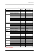
Rev. Description Date Page 61 62 63, 64 66 4.01 Dec 24, 2004 68 Summary Section “5.2.4 Precautions on Internal Reserved Area Expansion Bit” is added Description of Section “5.2.6” is changed ROM/RAM Area Table is upgrade Description of NMI pin is deleted from Section “5.4” Description of Realtime and Reset Vector Table in Section “5.5.3” is changed 76, 77 Section “6.
USB Flash Writer User's Manual Publication Date Rev.1.00 Oct 23, 2002 Rev.4.01 Dec 24, 2004 Published by: Renesas Solutions Corp. 4-1-6, Miyahara, Yodogawa-ku, Osaka City, 532-0003, Japan ©2004 Renesas Technology Corp. and Renesas Solutions Corp., All Rights Reserved. Printed in Japan.
USB Flash Writer User's Manual Renesas Solutions Corp.