REJ09B0112-0101Z M32R-FPU 32 Software Manual RENESAS 32-BIT RISC SINGLE-CHIP MICROCOMPUTER Before using this material, please visit our website to confirm that this is the most current document available. Rev. 1.01 Revision date: Oct 31, 2003 www.renesas.
Keep safety first in your circuit designs! • Renesas Technology Corporation puts the maximum effort into making semiconductor products better and more reliable, but there is always the possibility that trouble may occur with them. Trouble with semiconductors may lead to personal injury, fire or property damage.
M32R-FPU Software Manual REVISION HISTORY Rev. Date Description Summary Page 1.00 Jan 08, 2003 – 1.01 Oct 31, 2003 APPENDICES-3 APPENDICES-8 First edition issued Hexadecimal Instruction Code Table corrected (BTST instruction) Appendix Figure 3.1.1 corrected Incorrect) *The E1 stage of the FDIV instruction requires 13 cycles. Correct) *The E1 stage of the FDIV instruction requires 14 cycles. APPENDICES-10 Appendix Figure 3.2.1 corrected Incorrect) LD1 Correct) LDI APPENDICES-13 Appendix Figure 3.2.
Table of contents CHAPTER 1 CPU PROGRAMMING MODEL 1.1 CPU register .......................................................................................................... 1-2 1.2 General-purpose registers ...................................................................................... 1-2 1.3 Control registers ..................................................................................................... 1-3 1.3.1 Processor status word register: PSW (CR0) ....................................
CHAPTER 3 INSTRUCTIONS 3.1 Conventions for instruction description ................................................................... 3-2 3.2 Instruction description ............................................................................................. 3-5 APPENDIX Appendix 1 Hexadecimal Instraction Code .................................................................. Appendix-2 Appendix 2 Instruction List ...........................................................................................
This page left blank intentionally. M32R-FPU Software Manual (Rev.1.
CHAPTER 1 CPU PROGRAMMIING MODEL 1.1 1.2 1.3 1.4 1.5 1.6 1.
CPU PROGRAMMING MODEL 1 1.1 CPU Register 1.1 CPU Register The M32R family CPU, with a built-in FPU (herein referred to as M32R-FPU) has 16 general-purpose registers, 6 control registers, an accumulator and a program counter. The accumulator is of 56-bit configuration, and all other registers are a 32bit configuration. 1.
CPU PROGRAMMING MODEL 1 1.3 Control Registers 1.3 Control Registers There are 6 control registers which are the Processor Status Word Register (PSW), the Condition Bit Register (CBR), the Interrupt Stack Pointer (SPI), the User Stack Pointer (SPU), the Backup PC (BPC) and the Floating-point Status Register (FPSR). The dedicated MVTC and MVFC instructions are used for writing and reading these control registers.
CPU PROGRAMMING MODEL 1 1.3 Control Registers 1.3.1 Processor Status Word Register: PSW (CR0) b0 1 2 3 4 5 6 7 8 9 10 11 12 13 14 b15 0 0 0 0 0 0 0 0 0 0 0 0 0 0 0 0 18 19 20 21 22 26 27 28 29 30 b31 0 0 0 0 0 b16 17 BSM BIE ? ? 0 0 0 0 0 23 24 25 BC SM IE ? 0 0 C BPSW field 0 PSW field < At reset release: "B'0000 0000 0000 0000 ??00 000? 0000 0000 > b 0-15 Bit Name Function R W No function assigned. Fix to "0".
CPU PROGRAMMING MODEL 1 1.3 Control Registers 1.3.2 Condition Bit Register: CBR (CR1) The Condition Bit Register (CBR) is derived from the PSW register by extracting its Condition (C) bit. The value written to the PSW register's C bit is reflected in this register. The register can only be read. (Writing to the register with the MVTC instruction is ignored.) At reset release, the value of CBR is "H'0000 0000". b0 b31 CBR 0 0 0 0 0 0 0 0 0 0 0 0 0 0 0 0 0 0 0 0 0 0 0 0 0 0 0 0 0 0 0 C 1.3.
CPU PROGRAMMING MODEL 1 1.3 Control Registers 1.3.
CPU PROGRAMMING MODEL 1 1.3 Control Registers 21 EV Invalid Operation Exception Enable Bit 0: Mask EIT processing to be executed when an R W invalid operation exception occurs 1: Execute EIT processing when an invalid operation exception occurs 22 No function assigned. Fix to "0". 23 DN Denormalized Number Zero Flash Bit (Note 2) 24 0: Handle the denormalized number as a 0 W denormalized number 1: Handle the denormalized number as zero CE 0: No unimplemented operation exception occurred .
CPU PROGRAMMING MODEL 1 1.3 Control Registers 1.3.6 Floating-point Exceptions (FPE) Floating-point Exception (FPE) occurs when Unimplemented Exception (UIPL) or one of the five exceptions specified in the IEEE754 standard (OVF/UDF/IXCT/ DIV0/IVLD) is detected. Each exception processing is outlined below. (1) Overflow Exception (OVF) The exception occurs when the absolute value of the operation result exceeds the largest describable precision in the floating-point format.
CPU PROGRAMMING MODEL 1 1.3 Control Registers (3) Inexact Exception (IXCT) The exception occurs when the operation result differs from a result led out with an infinite range of precision. The following table shows the operation results and the respective conditions in which each IXCT occurs.
CPU PROGRAMMING MODEL 1 1.3 Control Registers (5) Invalid Operation Exception (IVLD) The exception occurs when an invalid operation is executed. The following table shows the operation results and the respective conditions in which each IVLD occurs.
CPU PROGRAMMING MODEL 1 1.4 Accumulator 1.4 Accumulator The Accumulator (ACC) is a 56-bit register used for DSP function instructions. The accumulator is handled as a 64-bit register when accessed for read or write. When reading data from the accumulator, the value of bit 8 is sign-extended. When writing data to the accumulator, bits 0 to 7 are ignored. The accumulator is also used for the multiply instruction "MUL", in which case the accumulator value is destroyed by instruction execution.
CPU PROGRAMMING MODEL 1 1.6 Data Format 1.6 Data Format 1.6.1 Data Type The data types that can be handled by the M32R-FPU instruction set are signed or unsigned 8, 16, and 32-bit integers and single-precision floating-point numbers. The signed integers are represented by 2's complements.
CPU PROGRAMMING MODEL 1 1.6 Data Format 1.6.2 Data Format (1) Data format in a register The data sizes in the M32R-FPU registers are always words (32 bits). When loading byte (8-bit) or halfword (16-bit) data from memory into a register, the data is sign-extended (LDB, LDH instructions) or zero-extended (LDUB, LDUH instructions) to a word (32-bit) quantity before being loaded into the register.
CPU PROGRAMMING MODEL 1 1.6 Data Format (2) Data format in memory The data sizes in memory can be byte (8 bits), halfword (16 bits) or word (32 bits). Although byte data can be located at any address, halfword and word data must be located at the addresses aligned with a halfword boundary (least significant address bit = "0") or a word boundary (two low-order address bits = "00"), respectively.
CPU PROGRAMMING MODEL 1 1.7 Addressing Mode 1.7 Addressing Mode M32R-FPU supports the following addressing modes. (1) Register direct [R or CR] The general-purpose register or the control register to be processed is specified. (2) Register indirect [@R] The contents of the register specify the address of the memory. This mode can be used by all load/store instructions.
1 CPU PROGRAMMING MODEL 1.7 Addressing Mode This page left blank intentionally. 1-16 M32R-FPU Software Manual (Rev.1.
CHAPTER 2 INSTRUCTION SET 2.1 Instruction set overview 2.
INSTRUCTION SET 2 2.1 Instruction set overview 2.1 Instruction set overview The M32R-FPU has a total of 100 instructions. The M32R-FPU has a RISC architecture. Memory is accessed by using the load/store instructions and other operations are executed by using register-to-register operation instructions. M32R CPU supports compound instructions such as " load & address update" and "store & address update" which are useful for high-speed data transfer. 2.1.
INSTRUCTION SET 2 2.1 Instruction set overview Three types of addressing modes can be specified for load/store instructions. (1) Register indirect The contents of the register specify the address. This mode can be used by all load/ store instructions. (2) Register relative indirect (The contents of the register) + (32-bit sign-extended 16-bit immediate value) specifies the address. This mode can be used by all except LOCK and UNLOCK instructions.
INSTRUCTION SET 2 2.1 Instruction set overview 2.1.2 Transfer instructions The transfer instructions carry out data transfers between registers or a register and an immediate value. LD24 LDI MV MVFC MVTC SETH Load 24-bit immediate Load immediate Move register Move from control register Move to control register Set high-order 16-bit 2.1.3 Operation instructions Compare, arithmetic/logic operation, multiply and divide, and shift are carried out between registers.
INSTRUCTION SET 2 2.
INSTRUCTION SET 2 2.1 Instruction set overview 2.1.4 Branch instructions The branch instructions are used to change the program flow.
INSTRUCTION SET 2 2.1 Instruction set overview The addressing mode of the BRA, BL, BC and BNC instructions can specify an 8-bit or 24-bit immediate value. The addressing mode of the BEQ, BNE, BEQZ, BNEZ, BLTZ, BGEZ, BLEZ, and BGTZ instructions can specify a 16-bit immediate value. In the JMP and JL instructions, the register value becomes the branch address. However, the low-order 2-bit value of the register is ignored.
INSTRUCTION SET 2 2.1 Instruction set overview 2.1.5 EIT-related instructions The EIT-related instructions carry out the EIT events (Exception, Interrupt and Trap). Trap initiation and return from EIT are EIT-related instructions. TRAP RTE Trap Return from EIT 2.1.
INSTRUCTION SET 2 2.
INSTRUCTION SET 2 2.1 Instruction set overview < word size round off > < halfword size round off > 0 63 0 63 ACC ACC RACH instruction RAC instruction 0 63 data sign 0 0 63 data sign 0 Note: The actual operation is processed in two steps. Refer to Chapter 3 for details. Fig. 2.1.
INSTRUCTION SET 2 2.1 Instruction set overview 2.1.7 Floating-point Instructions The following instructions execute floating-point operations.
INSTRUCTION SET 2 2.2 Instruction format 2.2 Instruction format There are two major instruction formats: two 16-bit instructions packed together within a word boundary, and a single 32-bit instruction (see Figure 2.2.1). Figure 2.2.2 shows the instruction format of M32R CPU. 1 word +0 address +1 +2 16-bit instruction A +3 16-bit instruction B 1 word address +0 +1 +2 +3 32-bit instruction Fig. 2.2.
INSTRUCTION SET 2 2.2 Instruction format The MSB (Most Significant Bit) of a 32-bit instruction is always "1". The MSB of a 16-bit instruction in the high-order halfword is always "0" (instruction A in Figure 2.2.3), however the processing of the following 16-bit instruction depends on the MSB of the instruction. In Figure 2.2.3, if the MSB of the instruction B is "0", instructions A and B are executed sequentially; B is executed after A.
INSTRUCTION SET 2 2.2 Instruction format This page left blank intentionally. 2-14 M32R-FPU Software Manual (Rev.1.
CHAPTER 3 INSTRUCTIONS 3.1 Conventions for instruction description 3.
INSTRUCTIONS 3 3.1 Conventions for instruction description 3.1 Conventions for instruction description Conventions for instruction description are summarized below. [Mnemonic] Shows the mnemonic and possible operands (operation target) using assembly language notation. Table 3.1.
INSTRUCTIONS 3 3.1 Conventions for instruction description Table 3.1.3 Operation expression (operator) (cont.
INSTRUCTIONS 3 3.1 Conventions for instruction description [Description] Describes the operation performed by the instruction and any condition bit change. [EIT occurrence] Shows possible EIT events (Exception, Interrupt, Trap) which may occur as the result of the instruction's execution. Only address exception (AE), floating-point exception (FPE) and trap (TRAP) may result from an instruction execution. [Instruction format] Shows the bit level instruction pattern (16 bits or 32 bits).
INSTRUCTIONS 3 3.2 Instruction description 3.2 Instruction description This section lists M32R-FPU instructions in alphabetical order. Each page is laid out as shown below.
INSTRUCTIONS 3 3.2 Instruction description arithmetic/logic operation ADD Add ADD [Mnemonic] ADD Rdest,Rsrc [Function] Add Rdest = Rdest + Rsrc; [Description] ADD adds Rsrc to Rdest and puts the result in Rdest. The condition bit (C) is unchanged. [EIT occurrence] None [Encoding] 0000 dest 1010 src ADD Rdest,Rsrc 3-6 M32R-FPU Software Manual (Rev.1.
INSTRUCTIONS 3 3.2 Instruction description arithmetic operation instruction ADD3 Add 3-operand ADD3 [Mnemonic] ADD3 Rdest,Rsrc,#imm16 [Function] Add Rdest = Rsrc + ( signed short ) imm16; [Description] ADD3 adds the 16-bit immediate value to Rsrc and puts the result in Rdest. The immediate value is sign-extended to 32 bits before the operation. The condition bit (C) is unchanged.
INSTRUCTIONS 3 3.2 Instruction description arithmetic operation instruction ADDI Add immediate ADDI [Mnemonic] ADDI Rdest,#imm8 [Function] Add Rdest = Rdest + ( signed char ) imm8; [Description] ADDI adds the 8-bit immediate value to Rdest and puts the result in Rdest. The immediate value is sign-extended to 32 bits before the operation. The condition bit (C) is unchanged. [EIT occurrence] None [Encoding] 0100 dest imm8 ADDI Rdest,#imm8 3-8 M32R-FPU Software Manual (Rev.1.
INSTRUCTIONS 3 3.2 Instruction description arithmetic operation instruction ADDV Add with overflow checking ADDV [Mnemonic] ADDV Rdest,Rsrc [Function] Add Rdest = ( signed ) Rdest + ( signed ) Rsrc; C = overflow ? 1 : 0; [Description] ADDV adds Rsrc to Rdest and puts the result in Rdest. The condition bit (C) is set when the addition results in overflow; otherwise it is cleared. [EIT occurrence] None [Encoding] 0000 dest 1000 src ADDV Rdest,Rsrc 3-9 M32R-FPU Software Manual (Rev.1.
INSTRUCTIONS 3 3.2 Instruction description ADDV3 arithmetic operation instruction Add 3-operand with overflow checking ADDV3 [Mnemonic] ADDV3 Rdest,Rsrc,#imm16 [Function] Add Rdest = ( signed ) Rsrc + ( signed ) ( ( signed short ) imm16 ); C = overflow ? 1 : 0; [Description] ADDV3 adds the 16-bit immediate value to Rsrc and puts the result in Rdest. The immediate value is sign-extended to 32 bits before it is added to Rsrc.
INSTRUCTIONS 3 3.2 Instruction description arithmetic operation instruction ADDX Add with carry ADDX [Mnemonic] ADDX Rdest,Rsrc [Function] Add Rdest = ( unsigned ) Rdest + ( unsigned ) Rsrc + C; C = carry_out ? 1 : 0; [Description] ADDX adds Rsrc and C to Rdest, and puts the result in Rdest. The condition bit (C) is set when the addition result cannot be represented by a 32-bit unsigned integer; otherwise it is cleared.
INSTRUCTIONS 3 3.2 Instruction description logic operation instruction AND AND AND [Mnemonic] AND Rdest,Rsrc [Function] Logical AND Rdest = Rdest & Rsrc; [Description] AND computes the logical AND of the corresponding bits of Rdest and Rsrc and puts the result in Rdest. The condition bit (C) is unchanged. [EIT occurrence] None [Encoding] 0000 dest 1100 src AND Rdest,Rsrc 3-12 M32R-FPU Software Manual (Rev.1.
INSTRUCTIONS 3 3.2 Instruction description logic operation instruction AND3 AND 3-operand AND3 [Mnemonic] AND3 Rdest,Rsrc,#imm16 [Function] Logical AND Rdest = Rsrc & ( unsigned short ) imm16; [Description] AND3 computes the logical AND of the corresponding bits of Rsrc and the 16-bit immediate value, which is zero-extended to 32 bits, and puts the result in Rdest. The condition bit (C) is unchanged.
INSTRUCTIONS 3 3.2 Instruction description branch instruction BC BC Bit clear M32R-FPU Extended Instruction [Mnemonic] (1) (2) BC BC pcdisp8 pcdisp24 [Function] Branch (1) if ( C==1 ) PC = ( PC & 0xfffffffc ) + ( ( ( signed char ) pcdisp8 ) << 2 ); (2) if ( C==1 ) PC = ( PC & 0xfffffffc ) + ( sign_extend ( pcdisp24 ) << 2 ); where #define sign_extend(x) ( ( ( signed ) ( (x)<< 8 ) ) >>8 ) [Description] BC causes a branch to the specified label when the condition bit (C) is 1.
INSTRUCTIONS 3 3.2 Instruction description bit operation BCLR Bit clear [M32R-FPU Extended Instruction] BCLR [Mnemonic] BCLR #bitpos,@(disp16,Rsrc) [Function] Bit operation for memory contents Set 0 to specified bit.
INSTRUCTIONS 3 3.2 Instruction description branch instruction BEQ Branch on equal to BEQ [Mnemonic] BEQ Rsrc1,Rsrc2,pcdisp16 [Function] Branch if ( Rsrc1 == Rsrc2 ) PC = ( PC & 0xfffffffc ) + ( ( ( signed short ) pcdisp16 ) << 2); [Description] BEQ causes a branch to the specified label when Rsrc1 is equal to Rsrc2. The condition bit (C) is unchanged. [EIT occurrence] None [Encoding] 1011 src1 0000 src2 BEQ pcdisp16 Rsrc1,Rsrc2,pcdisp16 3-16 M32R-FPU Software Manual (Rev.1.
INSTRUCTIONS 3 3.2 Instruction description branch instruction BEQZ Branch on equal to zero BEQZ [Mnemonic] BEQZ Rsrc,pcdisp16 [Function] Branch if ( Rsrc == 0 ) PC = ( PC & 0xfffffffc ) + ( ( ( signed short ) pcdisp16 ) << 2); [Description] BEQZ causes a branch to the specified label when Rsrc is equal to zero. The condition bit (C) is unchanged. [EIT occurrence] None [Encoding] 1011 0000 1000 BEQZ src pcdisp16 Rsrc,pcdisp16 3-17 M32R-FPU Software Manual (Rev.1.
INSTRUCTIONS 3 3.2 Instruction description branch instruction BGEZ Branch on greater than or equal to zero BGEZ [Mnemonic] BGEZ Rsrc,pcdisp16 [Function] Branch if ( (signed) Rsrc >= 0 ) PC = ( PC & 0xfffffffc ) + ( ( ( signed short ) pcdisp16 ) << 2); [Description] BGEZ causes a branch to the specified label when Rsrc treated as a signed 32-bit value is greater than or equal to zero. The condition bit (C) is unchanged.
INSTRUCTIONS 3 3.2 Instruction description branch instruction BGTZ Branch on greater than zero BGTZ [Mnemonic] BGTZ Rsrc,pcdisp16 [Function] Branch if ((signed) Rsrc > 0) PC = (PC & 0xfffffffc) + ( ( (signed short) pcdisp16 ) << 2); [Description] BGTZ causes a branch to the specified label when Rsrc treated as a signed 32-bit value is greater than zero. The condition bit (C) is unchanged.
INSTRUCTIONS 3 3.
INSTRUCTIONS 3 3.2 Instruction description branch instruction BLEZ Branch on less than or equal to zero BLEZ [Mnemonic] BLEZ Rsrc,pcdisp16 [Function] Branch if ((signed) Rsrc <= 0) PC = (PC & 0xfffffffc) + (((signed short) pcdisp16) << 2); [Description] BLEZ causes a branch to the specified label when the contents of Rsrc treated as a signed 32bit value, is less than or equal to zero. The condition bit (C) is unchanged.
INSTRUCTIONS 3 3.2 Instruction description branch instruction BLTZ Branch on less than zero BLTZ [Mnemonic] BLTZ Rsrc,pcdisp16 [Function] Branch if ((signed) Rsrc < 0) PC = (PC & 0xfffffffc) + (((signed short) pcdisp16) << 2); [Description] BLTZ causes a branch to the specified label when Rsrc treated as a signed 32-bit value is less than zero. The condition bit (C) is unchanged.
INSTRUCTIONS 3 3.2 Instruction description branch instruction BNC BNC Branch on not C-bit [Mnemonic] (1) (2) BNC BNC pcdisp8 pcdisp24 [Function] Branch (1) if (C==0) PC = ( PC & 0xfffffffc ) + ( ( ( signed char ) pcdisp8 ) << 2 ); (2) if (C==0) PC = ( PC & 0xfffffffc ) + ( sign_extend ( pcdisp24 ) << 2 ); where #define sign_extend(x) ( ( ( signed ) ( (x)<< 8 ) ) >>8 ) [Description] BNC branches to the specified label when the condition bit (C) is 0.
INSTRUCTIONS 3 3.2 Instruction description branch instruction BNE Branch on not equal to BNE [Mnemonic] BNE Rsrc1,Rsrc2,pcdisp16 [Function] Branch if ( Rsrc1 != Rsrc2 ) PC = ( PC & 0xfffffffc ) + ((( signed short ) pcdisp16) << 2); [Description] BNE causes a branch to the specified label when Rsrc1 is not equal to Rsrc2. The condition bit (C) is unchanged. [EIT occurrence] None [Encoding] 1011 src1 0001 src2 BNE pcdisp16 Rsrc1,Rsrc2,pcdisp16 3-24 M32R-FPU Software Manual (Rev.1.
INSTRUCTIONS 3 3.2 Instruction description branch instruction BNEZ Branch on not equal to zero BNEZ [Mnemonic] BNEZ Rsrc,pcdisp16 [Function] Branch if ( Rsrc != 0 ) PC = ( PC & 0xfffffffc ) + ( ( ( signed short ) pcdisp16 ) << 2); [Description] BNEZ causes a branch to the specified label when Rsrc is not equal to zero. The condition bit (C) is unchanged. [EIT occurrence] None [Encoding] 1011 0000 1001 src pcdisp16 BNEZ Rsrc,pcdisp16 3-25 M32R-FPU Software Manual (Rev.1.
INSTRUCTIONS 3 3.2 Instruction description branch instruction BRA BRA Branch [Mnemonic] (1) (2) BRA BRA pcdisp8 pcdisp24 [Function] Branch (1) PC = ( PC & 0xfffffffc ) + ( ( ( signed char ) pcdisp8 ) << 2 ); (2) PC = ( PC & 0xfffffffc ) + ( sign_extend ( pcdisp24 ) << 2 ); where #define sign_extend(x) ( ( ( signed ) ( (x)<< 8 ) ) >>8 ) [Description] BRA causes an unconditional branch to the address specified by the label.
INSTRUCTIONS 3 3.2 Instruction description bit operation Instructions BSET Bit set [M32R-FPU Extended Instruction] BSET [Mnemonic] BSET #bitpos,@(disp16,Rsrc) [Function] Bit operation for memory contents Set 0 to specified bit.
INSTRUCTIONS 3 3.2 Instruction description bit operation Instructions BTST Bit test [M32R-FPU Extended Instruction] BTST [Mnemonic] BTST #bitpos,Rsrc [Function] Remove the bit specified by the register. C = Rsrc >> ( 7-bitpos ) ) &1; [Description] Take out the bit specified as bitpos within the Rsrc lower eight bits and sets it in the condition bit (C). bitpos becomes 0 to 7, MSB becomes 0 and LSB becomes 7.
INSTRUCTIONS 3 3.2 Instruction description CLRPSW bit operation Instructions Clear PSW [M32R-FPU Extended Instruction] CLRPSW [Mnemonic] CLRPSW #imm8 [Function] Set the undefined SM, IE, and C bits of PSW to 0. PSW& = ~imm8 : 0xffffff00 [Description] Set the AND result s of the reverse value of b0 (MSB), b1, and b7 (LSB) of the 8-bit immediate value and bits SM, IE, and C of PSW to the corresponding SM, IE, and C bits. When b7 (LSB) or #imm8 is 1, the condition bit (C) goes to 0.
INSTRUCTIONS 3 3.2 Instruction description compare instruction CMP CMP Compare [Mnemonic] CMP Rsrc1,Rsrc2 [Function] Compare C = ( ( signed ) Rsrc1 < ( signed ) Rsrc2 ) ? 1:0; [Description] The condition bit (C) is set to 1 when Rsrc1 is less than Rsrc2. The operands are treated as signed 32-bit values. [EIT occurrence] None [Encoding] 0000 src1 0100 src2 CMP Rsrc1,Rsrc2 3-30 M32R-FPU Software Manual (Rev.1.
INSTRUCTIONS 3 3.2 Instruction description compare instruction CMPI Compare immediate CMPI [Mnemonic] CMPI Rsrc,#imm16 [Function] Compare C = ( ( signed ) Rsrc < ( signed short ) imm16 ) ? 1:0; [Description] The condition bit (C) is set when Rsrc is less than 16-bit immediate value. The operands are treated as signed 32-bit values. The immediate value is sign-extended to 32-bit before the operation.
INSTRUCTIONS 3 3.2 Instruction description compare instruction CMPU Compare unsigned CMPU [Mnemonic] CMPU Rsrc1,Rsrc2 [Function] Compare C = ( ( unsigned ) Rsrc1 < ( unsigned ) Rsrc2 ) ? 1:0; [Description] The condition bit (C) is set when Rsrc1 is less than Rsrc2. The operands are treated as unsigned 32-bit values. [EIT occurrence] None [Encoding] 0000 src1 0101 src2 CMPU 3-32 Rsrc1,Rsrc2 M32R-FPU Software Manual (Rev.1.
INSTRUCTIONS 3 3.2 Instruction description compare instruction CMPUI Compare unsigned immediate CMPUI [Mnemonic] CMPUI Rsrc,#imm16 [Function] Compare C = ( ( unsigned ) Rsrc < ( unsigned ) ( ( signed short ) imm16 ) ) ? 1:0; [Description] The condition bit (C) is set when Rsrc is less than the 16-bit immediate value. The operands are treated as unsigned 32-bit values. The immediate value is sign-extended to 32-bit before the operation.
INSTRUCTIONS 3 3.2 Instruction description multiply and divide instruction DIV Divide DIV [Mnemonic] DIV Rdest,Rsrc [Function] Signed division Rdest = ( signed ) Rdest / ( signed ) Rsrc; [Description] DIV divides Rdest by Rsrc and puts the quotient in Rdest. The operands are treated as signed 32-bit values and the result is rounded toward zero. The condition bit (C) is unchanged. When Rsrc is zero, Rdest is unchanged.
INSTRUCTIONS 3 3.2 Instruction description multiply and divide instruction DIVU Divide unsigned DIVU [Mnemonic] DIVU Rdest,Rsrc [Function] Unsigned division Rdest = ( unsigned ) Rdest / ( unsigned ) Rsrc; [Description] DIVU divides Rdest by Rsrc and puts the quotient in Rdest. The operands are treated as unsigned 32-bit values and the result is rounded toward zero. The condition bit (C) is unchanged. When Rsrc is zero, Rdest is unchanged.
INSTRUCTIONS 3 3.2 Instruction description floating-point Instructions FADD Floating-point add [M32R-FPU Extended Instruction] FADD [Mnemonic] FADD Rdest,Rsrc1,Rsrc2 [Function] Floating-point add Rdest = Rsrc1 + Rsrc2 ; [Description] Add the floating-point single precision values stored in Rsrc1 and Rsrc2 and store the result in Rdest. The result is rounded according to the RM field of FPSR. The DN bit of FPSR handles the modification of denormalized numbers.
INSTRUCTIONS 3 3.2 Instruction description floating point Instructions FADD FADD Floating-point addd [M32R-FPU Extended Instruction] [Supplemental Operation Description] The following shows the values of Rsrc1 and Rsrc2 and the operation results when DN = 0 and DN = 1.
INSTRUCTIONS 3 3.2 Instruction description floating point Instructions FCMP Floating-point compare [M32R-FPU Extended Instruction] FCMP [Mnemonic] FCMP Rdest,Rsrc1,Rsrc2 [Function] Floating-point compare Rdest = (comparison results of Rsrc1 and Rsrc2); When at least one value, either Rsrc1 or Rsrc2, is SNaN, a floating-point exception (other than Invalid Operation Exception) occurs.
INSTRUCTIONS 3 3.2 Instruction description floating point Instructions FCMP FCMP Floating-point compare [M32R-FPU Extended Instruction] [Supplemental Operation Description] The following shows the values of Rsrc1 and Rsrc2 and the operation results when DN = 0 and DN = 1.
INSTRUCTIONS 3 3.2 Instruction description FCMPE floating-point Instructions Floating-point compare with exception if unordered [M32R-FPU Extended Instruction] FCMPE [Mnemonic] FCMPE Rdest,Rsrc1,Rsrc2 [Function] Floating-point compare Rdest = (comparison results of Rsrc1 and Rsrc2); When at least one value, either Rsrc1 or Rsrc2, is QNaN or SNaN, a floating-point exception (other than Invalid Operation Exception) occurs.
INSTRUCTIONS 3 3.2 Instruction description floating point Instructions FCMPE FCMPE Floating-point compare with exception if unordered [M32R-FPU Extended Instruction] [Supplemental Operation Description] The following shows the values of Rsrc1 and Rsrc2 and the operation results when DN = 0 and DN = 1.
INSTRUCTIONS 3 3.2 Instruction description floating-point Instructions FDIV Floating-point divide [M32R-FPU Extended Instruction] FDIV [Mnemonic] FDIV Rdest,Rsrc1,Rsrc2 [Function] Floating-point divide Rdest = Rsrc1 / Rsrc2 ; [Description] Divide the floating-point single precision value stored in Rsrc1 by the floating-point single precision value stored in Rsrc1 and store the result in Rdest. The result is rounded according to the RM field of FPSR.
INSTRUCTIONS 3 3.2 Instruction description floating point Instructions FDIV FDIV Floating-point divide [M32R-FPU Extended Instruction] [Supplemental Operation Description] The following shows the values of Rsrc1 and Rsrc2 and the operation results when DN = 0 and DN = 1.
INSTRUCTIONS 3 3.2 Instruction description FMADD floating-point Instructions Floating-point multiply and add [M32R-FPU Extended Instruction] FMADD [Mnemonic] FMADD Rdest,Rsrc1,Rsrc2 [Function] Floating-point multiply and add Rdest = Rdest + Rsrc1 * Rsrc2 ; [Description] This instruction is executed in the following 2 steps. ● Step 1 Multiply the floating-point single precision value stored in Rsrc1 by the floating-point single precision value stored in Rsrc2.
INSTRUCTIONS 3 3.2 Instruction description floating point Instructions FMADD FMADD Floating-point multiply and add [M32R-FPU Extended Instruction] [Supplemental Operation Description] The following shows the values of Rsrc1, Rsrc2 and Rdest and the operation results when DN = 0 and DN = 1.
INSTRUCTIONS 3 3.
INSTRUCTIONS 3 3.2 Instruction description FMSUB floating-point Instructions Floating-point multiply and subtract [M32R-FPU Extended Instruction] FMSUB [Mnemonic] FMSUB Rdest,Rsrc1,Rsrc2 [Function] Floating-point multiply and subtract Rdest = Rdest - Rsrc1 * Rsrc2 ; [Description] This instruction is executed in the following 2 steps. ● Step 1 Multiply the floating-point single precision value stored in Rsrc1 by the floating-point single precision value stored in Rsrc2.
INSTRUCTIONS 3 3.2 Instruction description floating point Instructions FMSUB FMSUB Floating-point multiply and subtract [M32R-FPU Extended Instruction] [Supplemental Operation Description] The following shows the values of Rsrc1, Rsrc2 and Rdest and the operation results when DN = 0 and DN = 1.
INSTRUCTIONS 3 3.
INSTRUCTIONS 3 3.2 Instruction description floating-point Instructions FMUL Floating-point multiply [M32R-FPU Extended Instruction] FMUL [Mnemonic] FMUL Rdest,Rsrc1,Rsrc2 [Function] Floating-point multiply Rdest = Rsrc1 * Rsrc2 ; [Description] Multiply the floating-point single precision value stored in Rsrc1 by the floating-point single precision value stored in Rsrc2 and store the results in Rdest. The result is rounded according to the RM field of FPSR.
INSTRUCTIONS 3 3.2 Instruction description floating point Instructions FMUL FMUL Floating-point multiply [M32R-FPU Extended Instruction] [Supplemental Operation Description] The following shows the values of Rsrc1 and Rsrc2 and the operation results when DN = 0 and DN = 1.
INSTRUCTIONS 3 3.2 Instruction description floating-point Instructions FSUB Floating-point subtract [M32R-FPU Extended Instruction] FSUB [Mnemonic] FSUB Rdest,Rsrc1,Rsrc2 [Function] Floating-point subtract Rdest = Rsrc1 - Rsrc2 ; [Description] Subtract the floating-point single precision value stored in Rsrc2 from the floating-point single precision value stored in Rsrc1 and store the results in Rdest. The result is rounded according to the RM field of FPSR.
INSTRUCTIONS 3 3.2 Instruction description floating point Instructions FSUB FSUB Floating-point subtract [M32R-FPU Extended Instruction] [Supplemental Operation Description] The following shows the values of Rsrc1 and Rsrc2 and the operation results when DN = 0 and DN = 1.
INSTRUCTIONS 3 3.2 Instruction description floating-point Instructions FTOI Float to Integer [M32R-FPU Extended Instruction] FTOI [Mnemonic] FTOI Rdest,Rsrc [Function] Convert the floating-point single precision value to 32-bit integer. Rdest = (signed int) Rsrc ; [Description] Convert the floating-point single precision value stored in Rsrc to a 32-bit integer and store the result in Rdest. The result is rounded toward 0 regardless of the value in the RM field of FPSR.
INSTRUCTIONS 3 3.2 Instruction description floating point Instructions FTOI FTOI Float to Integer [M32R-FPU Extended Instruction] [Supplemental Operation Description] The results of the FTOI instruction executed based on the Rsrc value, both when DN = 0 and DN = 1, are shown in below.
INSTRUCTIONS 3 3.2 Instruction description floating-point Instructions FTOS Float to short [M32R-FPU Extended Instruction] FTOS [Mnemonic] FTOS Rdest,Rsrc [Function] Convert the floating-point single precision value to 16-bit integer. Rdest = (signed int) Rsrc ; [Description] Convert the floating-point single precision value stored in Rsrc to a 16-bit integer and store the result in Rdest. The result is rounded toward 0 regardless of the value in the RM field of FPSR.
INSTRUCTIONS 3 3.2 Instruction description floating point Instructions FTOS FTOS Float to short [M32R-FPU Extended Instruction] [Supplemental Operation Description] The results of the FTOS instruction executed based on the Rsrc value, both when DN = 0 and DN = 1, are shown in below.
INSTRUCTIONS 3 3.2 Instruction description floating-point Instructions ITOF Integer to float [M32R-FPU Extended Instruction] ITOF [Mnemonic] ITOF Rdest,Rsrc [Function] Convert the integer to a floating-point single precision value. Rdes = (float) Rsrc ; [Description] Converts the 32-bit integer stored in Rsrc to a floating-point single precision value and stores the result in Rdest. The result is rounded according to the RM field of FPSR. The condition bit (C) remains unchanged.
INSTRUCTIONS 3 3.2 Instruction description branch instruction JL Jump and link JL [Mnemonic] JL Rsrc [Function] Subroutine call (register direct) R14 = ( PC & 0xfffffffc ) + 4; PC = Rsrc & 0xfffffffc; [Description] JL causes an unconditional jump to the address specified by Rsrc and puts the return address in R14. The condition bit (C) is unchanged. [EIT occurrence] None [Encoding] 0001 1110 1100 src JL Rsrc 3-59 M32R-FPU Software Manual (Rev.1.
INSTRUCTIONS 3 3.2 Instruction description branch instruction JMP JMP Jump [Mnemonic] JMP Rsrc [Function] Jump PC = Rsrc & 0xfffffffc; [Description] JMP causes an unconditional jump to the address specified by Rsrc. The condition bit (C) is unchanged. [EIT occurrence] None [Encoding] 0001 1111 1100 src JMP Rsrc 3-60 M32R-FPU Software Manual (Rev.1.
INSTRUCTIONS 3 3.2 Instruction description load/store instruction LD LD Load [Mnemonic] (1) (2) LD LD Rdest,@Rsrc Rdest,@Rsrc+ (3) LD Rdest,@(disp16,Rsrc) [Function] Load to register from the contents of the memory. (1) Rdest = *( int *) Rsrc; (2) Rdest = *( int *) Rsrc, Rsrc += 4; (3) Rdest = *( int *) ( Rsrc + ( signed short ) disp16 ); [Description] (1) The contents of the memory at the address specified by Rsrc are loaded into Rdest.
INSTRUCTIONS 3 3.2 Instruction description load/store instruction LD24 Load 24-bit immediate LD24 [Mnemonic] LD24 Rdest,#imm24 [Function] Load the 24-bit immediate value into register. Rdest = imm24 & 0x00ffffff; [Description] LD24 loads the 24-bit immediate value into Rdest. The immediate value is zero-extended to 32 bits. The condition bit (C) is unchanged. [EIT occurrence] None [Encoding] 1110 dest LD24 imm24 Rdest,#imm24 3-62 M32R-FPU Software Manual (Rev.1.
INSTRUCTIONS 3 3.2 Instruction description load/store instruction LDB LDB Load byte [Mnemonic] (1) (2) LDB LDB Rdest,@Rsrc Rdest,@(disp16,Rsrc) [Function] Load to register from the contents of the memory. (1) Rdest = *( signed char *) Rsrc; (2) Rdest = *( signed char *) ( Rsrc + ( signed short ) disp16 ); [Description] (1) LDB sign-extends the byte data of the memory at the address specified by Rsrc and loads it into Rdest.
INSTRUCTIONS 3 3.2 Instruction description load/store instruction LDH LDH Load halfword [Mnemonic] (1) (2) LDH LDH Rdest,@Rsrc Rdest,@(disp16,Rsrc) [Function] Load to register from the contents of the memory. (1) Rdest = *( signed short *) Rsrc; (2) Rdest = *( signed short *) ( Rsrc + ( signed short ) disp16 ); [Description] (1) LDH sign-extends the halfword data of the memory at the address specified by Rsrc and loads it into Rdest.
INSTRUCTIONS 3 3.2 Instruction description transfer instruction LDI LDI Load immediate [Mnemonic] (1) (2) LDI LDI Rdest,#imm8 Rdest,#imm16 [Function] Load the immediate value into register. (1) Rdest = ( signed char ) imm8; (2) Rdest = ( signed short ) imm16; [Description] (1) LDI loads the 8-bit immediate value into Rdest. The immediate value is sign-extended to 32 bits. (2) LDI loads the 16-bit immediate value into Rdest. The immediate value is sign-extended to 32 bits.
INSTRUCTIONS 3 3.2 Instruction description load/store instruction LDUB Load unsigned byte LDUB [Mnemonic] (1) (2) LDUB LDUB Rdest,@Rsrc Rdest,@(disp16,Rsrc) [Function] Load to register from the contents of the memory. (1) Rdest = *( unsigned char *) Rsrc; (2) Rdest = *( unsigned char *) ( Rsrc + ( signed short ) disp16 ); [Description] (1) LDUB zero-extends the byte data from the memory at the address specified by Rsrc and loads it into Rdest.
INSTRUCTIONS 3 3.2 Instruction description load/store instruction LDUH Load unsigned halfword LDUH [Mnemonic] (1) (2) LDUH LDUH Rdest,@Rsrc Rdest,@(disp16,Rsrc) [Function] Load to register from the contents of the memory. (1) Rdest = *( unsigned short *) Rsrc; (2) Rdest = *( unsigned short *) ( Rsrc + ( signed short ) disp16 ); [Description] (1) LDUH zero-extends the halfword data from the memory at the address specified by Rsrc and loads it into Rdest.
INSTRUCTIONS 3 3.2 Instruction description load/store instruction LOCK LOCK Load locked [Mnemonic] LOCK Rdest,@Rsrc [Function] Load locked LOCK = 1, Rdest = *( int *) Rsrc; [Description] The contents of the word at the memory location specified by Rsrc are loaded into Rdest. The condition bit (C) is unchanged. This instruction sets the LOCK bit in addition to simple loading. When the LOCK bit is 1, external bus master access is not accepted.
INSTRUCTIONS 3 3.2 Instruction description DSP function instruction Multiply-accumulate high-order halfwords MACHI MACHI [Mnemonic] MACHI Rsrc1,Rsrc2 [Function] Multiply and add accumulator += (( signed) (Rsrc1 & 0xffff0000) * (signed short) (Rsrc2 >> 16)); [Description] MACHI multiplies the high-order 16 bits of Rsrc1 and the high-order 16 bits of Rsrc2, then adds the result to the low-order 56 bits in the accumulator.
INSTRUCTIONS 3 3.2 Instruction description DSP function instruction MACLO Multiply-accumulate low-order halfwords MACLO [Mnemonic] MACLO Rsrc1,Rsrc2 [Function] Multiply and add accumulator += ( ( signed ) ( Rsrc1 << 16 ) * ( signed short ) Rsrc2 ) ; [Description] MACLO multiplies the low-order 16 bits of Rsrc1 and the low-order 16 bits of Rsrc2, then adds the result to the low order 56 bits in the accumulator.
INSTRUCTIONS 3 3.2 Instruction description MACWHI DSP function instruction Multiply-accumulate word and high-order halfword MACWHI [Mnemonic] MACWHI Rsrc1,Rsrc2 [Function] Multiply and add accumulator += ( ( signed ) Rsrc1 * ( signed short ) ( Rsrc2 >> 16 ) ); [Description] MACWHI multiplies the 32 bits of Rsrc1 and the high-order 16 bits of Rsrc2, then adds the result to the low-order 56 bits in the accumulator.
INSTRUCTIONS 3 3.2 Instruction description MACWLO DSP function instruction Multiply-accumulate word and low-order halfword MACWLO [Mnemonic] MACWLO Rsrc1,Rsrc2 [Function] Multiply and add accumulator += ( ( signed ) Rsrc1 * ( signed short ) Rsrc2 ) ; [Description] MACWLO multiplies the 32 bits of Rsrc1 and the low-order 16 bits of Rsrc2, then adds the result to the low-order 56 bits in the accumulator.
INSTRUCTIONS 3 3.2 Instruction description multiply and divide instruction MUL Multiply MUL [Mnemonic] MUL Rdest,Rsrc [Function] Multiply { signed64bit tmp; tmp = ( signed64bit ) Rdest * ( signed64bit ) Rsrc; Rdest = ( int ) tmp;} [Description] MUL multiplies Rdest by Rsrc and puts the result in Rdest. The operands are treated as signed values. The contents of the accumulator are destroyed by this instruction. The condition bit (C) is unchanged.
INSTRUCTIONS 3 3.2 Instruction description DSP function instruction MULHI Multiply high-order halfwords MULHI [Mnemonic] MULHI Rsrc1,Rsrc2 [Function] Multiply accumulator = (( signed) (Rsrc1 & 0xffff000 ) * (signed short) (Rsrc2 >> 16)); [Description] MULHI multiplies the high-order 16 bits of Rsrc1 and the high-order 16 bits of Rsrc2, and stores the result in the accumulator.
INSTRUCTIONS 3 3.2 Instruction description MULLO DSP function instruction Multiply low-order halfwords MULLO [Mnemonic] MULLO Rsrc1,Rsrc2 [Function] Multiply accumulator = ( ( signed ) ( Rsrc1 << 16 ) * ( signed short ) Rsrc2 ); [Description] MULLO multiplies the low-order 16 bits of Rsrc1 and the low-order 16 bits of Rsrc2, and stores the result in the accumulator.
INSTRUCTIONS 3 3.2 Instruction description MULWHI DSP function instruction Multiply word and high-order halfword MULWHI [Mnemonic] MULWHI Rsrc1,Rsrc2 [Function] Multiply accumulator = ( ( signed ) Rsrc1 * ( signed short ) ( Rsrc2 >> 16 ) ); [Description] MULWHI multiplies the 32 bits of Rsrc1 and the high-order 16 bits of Rsrc2, and stores the result in the accumulator.
INSTRUCTIONS 3 3.2 Instruction description MULWLO DSP fucntion instruction Multiply word and low-order halfword MULWLO [Mnemonic] MULWLO Rsrc1,Rsrc2 [Function] Multiply accumulator = ( ( signed ) Rsrc1 * ( signed short ) Rsrc2 ); [Description] MULWLO multiplies the 32 bits of Rsrc1 and the low-order 16 bits of Rsrc2, and stores the result in the accumulator.
INSTRUCTIONS 3 3.2 Instruction description transfer instruction MV MV Move register [Mnemonic] MV Rdest,Rsrc [Function] Transfer Rdest = Rsrc; [Description] MV moves Rsrc to Rdest. The condition bit (C) is unchanged. [EIT occurrence] None [Encoding] 0001 dest 1000 src MV Rdest,Rsrc 3-78 M32R-FPU Software Manual (Rev.1.
INSTRUCTIONS 3 3.2 Instruction description MVFACHI DSP function instruction Move high-order word from accumulator MVFACHI [Mnemonic] MVFACHI Rdest [Function] Transfer from accumulator to register Rdest = ( int ) ( accumulator >> 32 ) ; [Description] MVFACHI moves the high-order 32 bits of the accumulator to Rdest. The condition bit (C) is unchanged. [EIT occurrence] None [Encoding] 0101 dest 1111 0000 MVFACHI 3-79 Rdest M32R-FPU Software Manual (Rev.1.
INSTRUCTIONS 3 3.2 Instruction description MVFACLO DSP function instruction Move low-order word from accumulator MVFACLO [Mnemonic] MVFACLO Rdest [Function] Transfer from accumulator to register Rdest = ( int ) accumulator [Description] MVFACLO moves the low-order 32 bits of the accumulator to Rdest. The condition bit (C) is unchanged. [EIT occurrence] None [Encoding] 0101 dest 1111 0001 MVFACLO 3-80 Rdest M32R-FPU Software Manual (Rev.1.
INSTRUCTIONS 3 3.2 Instruction description MVFACMI DSP function instruction Move middle-order word from accumulator MVFACMI [Mnemonic] MVFACMI Rdest [Function] Transfer from accumulator to register Rdest = ( int ) ( accumulator >> 16 ) ; [Description] MVFACMI moves bits16 through 47 of the accumulator to Rdest. The condition bit (C) is unchanged. [EIT occurrence] None [Encoding] 0101 dest 1111 0010 MVFACMI 3-81 Rdest M32R-FPU Software Manual (Rev.1.
INSTRUCTIONS 3 3.2 Instruction description transfer instruction MVFC Move from control register MVFC [Mnemonic] MVFC Rdest,CRsrc [Function] Transfer from control register to register Rdest = CRsrc ; [Description] MVFC moves CRsrc to Rdest. The condition bit (C) is unchanged. [EIT occurrence] None [Encoding] 0001 dest 1001 src MVFC 3-82 Rdest,CRsrc M32R-FPU Software Manual (Rev.1.
INSTRUCTIONS 3 3.2 Instruction description MVTACHI DSP function instruction Move high-order word to accumulator MVTACHI [Mnemonic] MVTACHI Rsrc [Function] Transfer from register to accumulator accumulator [ 0 : 31 ] = Rsrc ; [Description] MVTACHI moves Rsrc to the high-order 32 bits of the accumulator. The condition bit (C) is unchanged. [EIT occurrence] None [Encoding] 0101 src 0111 0000 MVTACHI 3-83 Rsrc M32R-FPU Software Manual (Rev.1.
INSTRUCTIONS 3 3.2 Instruction description MVTACLO DSP function instruction Move low-order word to accumulator MVTACLO [Mnemonic] MVTACLO Rsrc [Function] Transfer from register to accumulator accumulator [ 32 : 63 ] = Rsrc ; [Description] MVTACLO moves Rsrc to the low-order 32 bits of the accumulator. The condition bit (C) is unchanged. [EIT occurrence] None [Encoding] 0101 src 0111 0001 MVTACLO 3-84 Rsrc M32R-FPU Software Manual (Rev.1.
INSTRUCTIONS 3 3.2 Instruction description transfer instruction MVTC Move to control register MVTC [Mnemonic] MVTC Rsrc,CRdest [Function] Transfer from register to control register CRdest = Rsrc ; [Description] MVTC moves Rsrc to CRdest. If PSW(CR0) is specified as CRdest, the condition bit (C) is changed; otherwise it is unchanged. [EIT occurrence] None [Encoding] 0001 dest 1010 src MVTC 3-85 Rsrc,CRdest M32R-FPU Software Manual (Rev.1.
INSTRUCTIONS 3 3.2 Instruction description arithmetic operation instruction NEG Negate NEG [Mnemonic] NEG Rdest,Rsrc [Function] Negate Rdest = 0 – Rsrc ; [Description] NEG negates (changes the sign of) Rsrc treated as a signed 32-bit value, and puts the result in Rdest. The condition bit (C) is unchanged. [EIT occurrence] None [Encoding] 0000 dest 0011 src NEG Rdest,Rsrc 3-86 M32R-FPU Software Manual (Rev.1.
INSTRUCTIONS 3 3.2 Instruction description NOP branch instruction NOP No operation [Mnemonic] NOP [Function] No operation /* */ [Description] NOP performs no operation. The subsequent instruction then processed. The condition bit (C) is unchanged. [EIT occurrence] None [Encoding] 0111 0000 0000 0000 NOP 3-87 M32R-FPU Software Manual (Rev.1.
INSTRUCTIONS 3 3.2 Instruction description logic operation instruction NOT Logical NOT NOT [Mnemonic] NOT Rdest,Rsrc [Function] Logical NOT Rdest = ~ Rsrc ; [Description] NOT inverts each of the bits of Rsrc and puts the result in Rdest. The condition bit (C) is unchanged. [EIT occurrence] None [Encoding] 0000 dest 1011 src NOT Rdest,Rsrc 3-88 M32R-FPU Software Manual (Rev.1.
INSTRUCTIONS 3 3.2 Instruction description logic operation instruction OR OR OR [Mnemonic] OR Rdest,Rsrc [Function] Logical OR Rdest = Rdest | Rsrc ; [Description] OR computes the logical OR of the corresponding bits of Rdest and Rsrc, and puts the result in Rdest. The condition bit (C) is unchanged. [EIT occurrence] None [Encoding] 0000 dest 1110 src OR Rdest,Rsrc 3-89 M32R-FPU Software Manual (Rev.1.
INSTRUCTIONS 3 3.2 Instruction description logic operation instruction OR3 OR 3-operand OR3 [Mnemonic] OR3 Rdest,Rsrc,#imm16 [Function] Logical OR Rdest = Rsrc | ( unsigned short ) imm16 ; [Description] OR3 computes the logical OR of the corresponding bits of Rsrc and the 16-bit immediate value, which is zero-extended to 32 bits, and puts the result in Rdest. The condition bit (C) is unchanged.
INSTRUCTIONS 3 3.
INSTRUCTIONS 3 3.2 Instruction description DSP function instruction RAC RAC Round accumulator [Supplement] This instruction is executed in two steps as shown below: 0 8 16 32 48 63 0 1-bit shift to the left supposed sign extended bit0-bit7 0 8 16 32 47 48 63 The value in the accumulator is altered depending on the supposed bit 80 through 7 after left-shift operation and bit 8 through bit 63 after shift operation.
INSTRUCTIONS 3 3.
INSTRUCTIONS 3 3.2 Instruction description DSP function instruction RACH RACH Round accumulator halfword [Supplement] This instruction is executed in two steps, as shown below. 0 8 16 32 48 63 0 1-bit shift to the left supposed sign extended bit0-bit7 0 8 16 32 47 48 63 The value in the accumulator is altered depending on the supposed bit 80 through 7 after left-shift operation and bit 8 through bit 63 after shift operation.
INSTRUCTIONS 3 3.2 Instruction description multiply and divide instruction REM Remainder REM [Mnemonic] REM Rdest,Rsrc [Function] Signed remainder Rdest = ( signed ) Rdest % ( signed ) Rsrc ; [Description] REM divides Rdest by Rsrc and puts the quotient in Rdest. The operands are treated as signed 32-bit values. The quotient is rounded toward zero and the quotient takes the same sign as the dividend. The condition bit (C) is unchanged. When Rsrc is zero, Rdest is unchanged.
INSTRUCTIONS 3 3.2 Instruction description multiply and divide instruction REMU Remainder unsigned REMU [Mnemonic] REMU Rdest,Rsrc [Function] Unsigned remainder Rdest = ( unsigned ) Rdest % ( unsigned ) Rsrc ; [Description] REMU divides Rdest by Rsrc and puts the quotient in Rdest. The operands are treated as unsigned 32-bit values. The condition bit (C) is unchanged. When Rsrc is zero, Rdest is unchanged.
INSTRUCTIONS 3 3.2 Instruction description EIT-related instruction RTE Return from EIT RTE [Mnemonic] RTE [Function] Return from EIT SM = BSM ; IE = BIE ; C = BC ; PC = BPC & 0xfffffffc ; [Description] RTE restores the SM, IE and C bits of the PSW from the BSM, BIE and BC bits, and jumps to the address specified by BPC. At this time, because the BSM, BIE, and BC bits in the PSW register are undefined, the BPC is also undefined.
INSTRUCTIONS 3 3.2 Instruction description Transfer instructions SETH Set high-order 16-bit SETH [Mnemonic] SETH Rdest,#imm16 [Function] Transfer instructions Rdest = ( signed short ) imm16 << 16 ; [Description] SETH load the immediate value into the 16 most significant bits of Rdest. The 16 least significant bits become zero. The condition bit (C) is unchanged. [EIT occurrence] None [Encoding] 1101 dest 1100 0000 SETH imm16 Rdest,#imm16 3-98 M32R-FPU Software Manual (Rev.1.
INSTRUCTIONS 3 3.2 Instruction description SETPSW Bit Operation Instructions Set PSW [M32R-FPU Extended Instruction] SETPSW [Mnemonic] SETPSW #imm8 [Function] Set the undefined SM, IE, anc C bits of PSW to 1. PSW : = imm8&0x000000ff [Description] Set the AND result of the value of b0 (MSB), b1, and b7 (LSB) of the 8-bit immediate value and bits SM, IE, and C of PSW to the corresponding SM, IE, and C bits. When b7 (LSB) or #imm8 is 1, the condition bit (C) goes to 0.
INSTRUCTIONS 3 3.2 Instruction description shift instruction SLL SLL Shift left logical [Mnemonic] SLL Rdest,Rsrc [Function] Logical left shift Rdest = Rdest << ( Rsrc & 31 ) ; [Description] SLL left logical-shifts the contents of Rdest by the number specified by Rsrc, shifting zeroes into the least significant bits. Only the five least significant bits of Rsrc are used. The condition bit (C) is unchanged.
INSTRUCTIONS 3 3.2 Instruction description shift instruction SLL3 Shift left logical 3-operand SLL3 [Mnemonic] SLL3 Rdest,Rsrc,#imm16 [Function] Logical left shift Rdest = Rsrc << ( imm16 & 31 ) ; [Description] SLL3 left logical-shifts the contents of Rsrc into Rdest by the number specified by the 16-bit immediate value, shifting zeroes into the least significant bits. Only the five least significant bits of the 16-bit immediate value are used. The condition bit (C) is unchanged.
INSTRUCTIONS 3 3.2 Instruction description shift instruction SLLI Shift left logical immediate SLLI [Mnemonic] SLLI Rdest,#imm5 [Function] Logical left shift Rdest = Rdest << imm5 ; [Description] SLLI left logical-shifts the contents of Rdest by the number specified by the 5-bit immediate value, shifting zeroes into the least significant bits. The condition bit (C) is unchanged. [EIT occurrence] None [Encoding] 0101 dest 010 imm5 SLLI Rdest,#imm5 3-102 M32R-FPU Software Manual (Rev.1.
INSTRUCTIONS 3 3.2 Instruction description shift instruction SRA Shift right arithmetic SRA [Mnemonic] SRA Rdest,Rsrc [Function] Arithmetic right shift Rdest = ( signed ) Rdest >> ( Rsrc & 31 ) ; [Description] SRA right arithmetic-shifts the contents of Rdest by the number specified by Rsrc, replicates the sign bit in the MSB of Rdest and puts the result in Rdest. Only the five least significant bits are used. The condition bit (C) is unchanged.
INSTRUCTIONS 3 3.2 Instruction description shift instruction SRA3 Shift right arithmetic 3-operand SRA3 [Mnemonic] SRA3 Rdest,Rsrc,#imm16 [Function] Arithmetic right shift Rdest = ( signed ) Rsrc >> ( imm16 & 31 ) ; [Description] SRA3 right arithmetic-shifts the contents of Rsrc into Rdest by the number specified by the 16bit immediate value, replicates the sign bit in Rsrc and puts the result in Rdest. Only the five least significant bits are used. The condition bit (C) is unchanged.
INSTRUCTIONS 3 3.2 Instruction description shift instruction SRAI Shift right arithmetic immediate SRAI [Mnemonic] SRAI Rdest,#imm5 [Function] Arithmetic right shift Rdest = ( signed ) Rdest >> imm5 ; [Description] SRAI right arithmetic-shifts the contents of Rdest by the number specified by the 5-bit immediate value, replicates the sign bit in MSB of Rdest and puts the result in Rdest. The condition bit (C) is unchanged.
INSTRUCTIONS 3 3.2 Instruction description shift instruction SRL SRL Shift right logical [Mnemonic] SRL Rdest,Rsrc [Function] Logical right shift Rdest = ( unsigned ) Rdest >> ( Rsrc & 31 ) ; [Description] SRL right logical-shifts the contents of Rdest by the number specified by Rsrc, shifts zeroes into the most significant bits and puts the result in Rdest. Only the five least significant bits of Rsrc are used. The condition bit (C) is unchanged.
INSTRUCTIONS 3 3.2 Instruction description shift instruction SRL3 Shift right logical 3-operand SRL3 [Mnemonic] SRL3 Rdest,Rsrc,#imm16 [Function] Logical right shift Rdest = ( unsigned ) Rsrc >> ( imm16 & 31 ) ; [Description] SRL3 right logical-shifts the contents of Rsrc into Rdest by the number specified by the 16-bit immediate value, shifts zeroes into the most significant bits. Only the five least significant bits of the immediate value are valid. The condition bit (C) is unchanged.
INSTRUCTIONS 3 3.2 Instruction description shift instruction SRLI Shift right logical immediate SRLI [Mnemonic] SRLI Rdest,#imm5 [Function] Logical right shift Rdest = ( unsigned ) Rdest >> ( imm5 & 31 ) ; [Description] SRLI right arithmetic-shifts Rdest by the number specified by the 5-bit immediate value, shifting zeroes into the most significant bits. The condition bit (C) is unchanged.
INSTRUCTIONS 3 3.2 Instruction description load/store instruction ST ST Store [Mnemonic] (1) (2) ST ST Rsrc1,@Rsrc2 Rsrc1,@+Rsrc2 (3) (4) ST ST Rsrc1,@-Rsrc2 Rsrc1,@(disp16,Rsrc2) [Function] Store (1) * ( int *) Rsrc2 = Rsrc1; (2) Rsrc2 += 4, * ( int *) Rsrc2 = Rsrc1; (3) Rsrc2 -= 4, * ( int *) Rsrc2 = Rsrc1; (4) * ( int *) ( Rsrc2 + ( signed short ) disp16 ) = Rsrc1; [Description] (1) ST stores Rsrc1 in the memory at the address specified by Rsrc2.
INSTRUCTIONS 3 3.2 Instruction description load/store instruction ST ST Store [Encoding] 0010 src1 0100 src2 ST Rsrc1,@Rsrc2 0010 src1 0110 src2 ST Rsrc1,@+Rsrc2 0010 src1 0111 src2 ST Rsrc1,@-Rsrc2 disp16 1010 src1 0100 src2 ST Rsrc1,@(disp16,Rsrc2) 3-110 M32R-FPU Software Manual (Rev.1.
INSTRUCTIONS 3 3.2 Instruction description load/store instruction STB STB Store byte [Mnemonic] (1) (2) STB STB Rsrc1,@Rsrc2 Rsrc1,@(disp16,Rsrc2) [Function] Store (1) * ( char *) Rsrc2 = Rsrc1; (2) * ( char *) ( Rsrc2 + ( signed short ) disp16 ) = Rsrc1; [Description] (1) STB stores the least significant byte of Rsrc1 in the memory at the address specified by Rsrc2.
INSTRUCTIONS 3 3.
INSTRUCTIONS 3 3.2 Instruction description arithmetic operation instruction SUB Subtract SUB [Mnemonic] SUB Rdest,Rsrc [Function] Subtract Rdest = Rdest - Rsrc; [Description] SUB subtracts Rsrc from Rdest and puts the result in Rdest. The condition bit (C) is unchanged. [EIT occurrence] None [Encoding] 0000 dest 0010 src SUB Rdest,Rsrc 3-113 M32R-FPU Software Manual (Rev.1.
INSTRUCTIONS 3 3.2 Instruction description arithmetic operation instruction SUBV Subtract with overflow checking SUBV [Mnemonic] SUBV Rdest,Rsrc [Function] Subtract Rdest = Rdest - Rsrc; C = overflow ? 1 : 0; [Description] SUBV subtracts Rsrc from Rdest and puts the result in Rdest. The condition bit (C) is set when the subtraction results in overflow; otherwise, it is cleared. [EIT occurrence] None [Encoding] 0000 dest 0000 src SUBV Rdest,Rsrc 3-114 M32R-FPU Software Manual (Rev.1.
INSTRUCTIONS 3 3.2 Instruction description arithmetic operation instruction SUBX Subtract with borrow SUBX [Mnemonic] SUBX Rdest,Rsrc [Function] Subtract Rdest = ( unsigned ) Rdest - ( unsigned ) Rsrc - C; C = borrow ? 1 : 0; [Description] SUBX subtracts Rsrc and C from Rdest and puts the result in Rdest. The condition bit (C) is set when the subtraction result cannot be represented by a 32-bit unsigned integer; otherwise it is cleared.
INSTRUCTIONS 3 3.2 Instruction description EIT-related instruction TRAP Trap TRAP [Mnemonic] TRAP #imm4 [Function] Trap occurrence BPC = PC + 4; BSM = SM; BIE = IE; BC = C ; IE = 0; C = 0; call_trap_handler( imm4 ); [Description] TRAP generates a trap with the trap number specified by the 4-bit immediate value. IE and C bits are cleared to "0". [EIT occurrence] Trap (TRAP) [Encoding] 0001 0000 1111 imm4 TRAP #imm4; 3-116 M32R-FPU Software Manual (Rev.1.
INSTRUCTIONS 3 3.2 Instruction description UNLOCK load/store instruction Store unlocked UNLOCK [Mnemonic] UNLOCK Rsrc1,@Rsrc2 [Function] Store unlocked if ( LOCK == 1 ) { * ( int *) Rsrc2 = Rsrc1; } LOCK = 0; [Description] When the LOCK bit is 1, the contents of Rsrc1 are stored at the memory location specified by Rsrc2. When the LOCK bit is 0, store operation is not executed. The condition bit (C) is unchanged.
INSTRUCTIONS 3 3.2 Instruction description Floating Point Instructions UTOF Unsigned integer to float [M32R-FPU Extended Instruction] UTOF [Mnemonic] UTOF Rdest,Rsrc [Function] Convert from unsigned integer to floating-point single precision value. Rdest = ( float ) ( unsigned int ) Rsrc ; [Description] UTOF converts the 32-bit unsigned integer stored in Rsrc to a floating-point single precision value, and the result is stored in Rdest. The result is rounded according to the RM field in FPSR.
INSTRUCTIONS 3 3.2 Instruction description logic operation instruction XOR Exclusive OR XOR [Mnemonic] XOR Rdest,Rsrc [Function] Exclusive OR Rdest = ( unsigned ) Rdest ^ ( unsigned ) Rsrc; [Description] XOR computes the logical XOR of the corresponding bits of Rdest and Rsrc, and puts the result in Rdest. The condition bit (C) is unchanged. [EIT occurrence] None [Encoding] 0000 dest 1101 src XOR Rdest,Rsrc 3-119 M32R-FPU Software Manual (Rev.1.
INSTRUCTIONS 3 3.2 Instruction description logic operation instruction XOR3 Exclusive OR 3-operand XOR3 [Mnemonic] XOR3 Rdest,Rsrc,#imm16 [Function] Exclusive OR Rdest = ( unsigned ) Rsrc ^ ( unsigned short ) imm16; [Description] XOR3 computes the logical XOR of the corresponding bits of Rsrc and the 16-bit immediate value, which is zero-extended to 32 bits, and puts the result in Rdest. The condition bit (C) is unchanged.
APPENDICES APPENDIX 1 APPENDIX 2 APPENDIX 3 APPENDIX 4 APPENDIX 5 APPENDIX 6 Hexadecimal Instraction Code Instruction List Pipeline Processing Instruction Execution Time IEEE754 Specification Overview M32R-FPU Specification Supplemental Explanation
APPENDIX 1 APPENDICES Appendix 1 Hexadecimal Instraction Code Appendix1 Hexadecimal Instraction Code The bit pattern of each instruction and correspondence of mnemonic are shown below. The instructions enclosed in the bold lines are M32R-FPU extended instructions. Appendix Table 1.1.
APPENDIX 1 APPENDICES Appendix 1 Hexadecimal Instraction Code 1000 1001 1010 1011 1100 1101 1110 1111 8 9 A B C D E F hexadecimal numeral ADD NOT AND XOR OR BTST Rdest,Rsrc Rdest,Rsrc Rdest,Rsrc Rdest,Rsrc Rdest,Rsrc #bitpos,Rsrc 0 0000 JL, JMP ( ✽ 1) RTE 1 0001 2 0010 3 0011 4 0100 5 0101 6 0110 MVFC MVTC Rdest,CRsrc Rsrc,CRdest LDB LDUB LDH LDUH LD LOCK LD Rdest,@Rsrc Rdest,@Rsrc Rdest,@Rsrc Rdest,@Rsrc Rdest,@Rsrc Rdest,@Rsrc Rdest,@Rsrc+
APPENDIX 2 APPENDICES Appendix 2 Instruction List Appendix 2 Instruction List The M32R-FPU instruction list is shown below (in alphabetical order).
APPENDIX 2 APPENDICES Appendix 2 Instruction List mnemonic function FMADD FMSUB FMUL FSUB FTOI FTOS Rdest,Rsrc1,Rsrc2 Rdest,Rsrc1,Rsrc2 Rdest,Rsrc1,Rsrc2 Rdest,Rsrc1,Rsrc2 Rdest,Rsrc Rdest,Rsrc Rdest Rdest Rdest Rdest Rdest Rdest ITOF Rdest,Rsrc Rdest = (float)Rsrc – JL JMP Rsrc Rsrc R14 = PC+4, PC = Rsrc PC = Rsrc – – LD LD LD Rdest,@(disp16,Rsrc) Rdest,@Rsrc Rdest,@Rsrc+ Rdest = *(s *)(Rsrc+(sh)disp16) Rdest = *(s *)Rsrc Rdest = *(s *)Rsrc, Rsrc += 4 – – – Rdest = imm24 & 0x00ffffff Rd
APPENDIX 2 APPENDICES Appendix 2 Instruction List mnemonic function condition bit (C) NEG NOP NOT Rdest,Rsrc Rdest,Rsrc Rdest = 0 - Rsrc /*no-operation*/ Rdest = ~Rsrc – – – OR OR3 Rdest,Rsrc Rdest,Rsrc,#imm16 Rdest = Rdest | Rsrc Rdest = Rsrc | (uh)imm16 – – RAC RACH REM REMU RTE Round the 32-bit value in the accumulator Round the 16-bit value in the accumulator Rdest,Rsrc Rdest = (s)Rdest % (s)Rsrc Rdest,Rsrc Rdest = (u)Rdest % (u)Rsrc PC = BPC & 0xfffffffc, PSW[SM,IE,C] = PSW[BSM,BIE,BC] S
APPENDIX 2 APPENDICES where: typedef typedef typedef typedef typedef typedef singed int unsigned int signed short unsigned short signed char unsigned char s; u; sh; uh; sb; ub; Appendix 2 Instruction List /* /* /* /* /* /* 32 32 16 16 8 8 bit bit bit bit bit bit signed integer (word)*/ unsigned integer (word)*/ signed integer (halfword)*/ unsigned integer (halfword)*/ signed integer (byte)*/ unsigned integer (byte)*/ APPENDICES-7 M32R-FPU Software Manual (Rev.1.
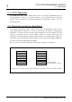
APPENDIX 3 APPENDICES Appendix 3 Pipeline Processing Appendix 3 Pipeline Processing Appendix 3.1 Instructions and Pipeline Processing Appendix Figure 3.1.1 shows each instruction type and the pipeline process. ■ Load/Store instruction 6 stages Pipeline Stage IF D E MEM1 MEM2 WB *The number of cycles required by the MEM1 stage varies according to the access, but the MEM2 stage is normally executed in 1 cycle.
APPENDIX 3 APPENDICES Appendix 3 Pipeline Processing The overview of each pipeline stage is shown below. ● IF stage (instruction fetch stage) The instruction fetch (IF) is processed in this stage. There is an instruction queue and instructions are fetched until the queue is full regardless of the completion of decoding in the D stage. If there is an instruction already in the instruction queue, the instruction read out of the instruction queue is passed to the instruction decoder.
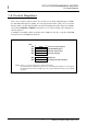
APPENDIX 3 APPENDICES Appendix 3 Pipeline Processing Appendix 3.2 Pipeline Basic Operation (1) Pipeline Flow with no Stall The following diagram shows an ideal pipeline flow that has no stall and executes each instruction in 1 clock cycle. (Since this is just an ideal case, all instructions may not be piplined in.
APPENDIX 3 APPENDICES Appendix 3 Pipeline Processing Three FPU instructions continue consecutively with no register dependency FADD R0,R5,R6 IF FSUB R1,R6,R7 D E1 E2 WB IF D E1 E2 WB IF D E1 E2 WB IF D E1 E2 FMUL R2,R7,R8 FCMP R0,R0,R3 WB * The FDIV instruction takes 14 cycles in E1 stage.
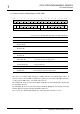
APPENDIX 3 APPENDICES Appendix 3 Pipeline Processing (2) Pipeline Flow with Stalls A pipeline stage may stall due to execution of a process or branch instruction. The following diagrams show typical stall cases.
APPENDIX 3 APPENDICES Appendix 3 Pipeline Processing A branch instruction is executed (except for the case in which no branch occurs at a conditional branch instruction) branch instruction is executed Branch Instruction IF D E WB IF D stall IF D E WB IF stall stall IF D E WB stall stall stall IF D E WB The subsequent instruction uses an operand read from the memory LD R1,@R2 IF D E MEM1 MEM2 WB Bypass process ADD R3,R1 LD R1,@R2 IF ADD R4,R5 IF D
APPENDIX 3 APPENDICES Appendix 3 Pipeline Processing The PSW is written by an MVTC, SETPSW, or CLRPSW instruction and the subsequent instruction reads R15 MVTC R1,PSW IF SUB R3,R15 D E WB IF D stall E WB FPSR is accessed by an MVFC instruction after the FPU instruction is executed FADD R0,R1,R2 IF MVFC R3,FPSR D E1 E2 WB IF D stall stall E WB The operation result of the FPU instruction is used by the subsequent instruction FADD R0,R1,R2 IF FADD R3,
APPENDIX 3 APPENDICES Appendix 3 Pipeline Processing The FPU and integer instructions run consecutively (with no register dependency) ADD R0,R1 IF FADD R2,R3,R4 D E WB IF D E1 E2 WB IF D stall E WB IF stall D E1 ADD R5,R6 FADD R7,R8,R9 E2 WB The FPU and integer instructions run consecutively (with register dependency) ADD R0,R1 IF D E WB Bypass process FADD ADD R0,R0,R4 IF R0,R6 FADD D E1 E2 WB IF D stall stall E WB Bypass process IF R0,R0,
APPENDIX 3 APPENDICES Appendix 3 Pipeline Processing The FPU and FMADD/FMSUB instructions run consecutively (with no register dependency) FADD R0,R1,R10 IF FMADD R2,R3,R4 D E1 E2 WB IF D EM EA E2 WB IF D stall E1 E2 WB IF stall D EM EA FADD R5,R6,R11 FMADD R7,R8,R9 E2 WB The FPU and FMADD/FMSUB instructions run consecutively (with register dependency) FADD R0,R1,R10 FMADD FADD R0,R0,R4 R0,R0,R11 FMADD R0,R8,R9 IF D E1 E2 WB IF D stall stall
APPENDIX 4 APPENDICES Appendix 4 Instruction Execution Time Appendix 4 Instruction Execution Time Normally, the E stage is considered as representing as the instruction execution time, however, because of the pipeline processing the execution time for other stages may effect the total instruction execution time. In particular, the IF, D, and E stages of the subsequent instruction must be considered after a branch has occurred.
APPENDIX 5 APPENDICES Appendix 5 IEEE754 Specification Overview Appendix 5 IEEE754 Specification Overview The following is a basic overview of the IEEE754 specification. M32R-FPU fulfills the IEEE754 requirements through a combination of software and hardware features. Appendix 5.1 Floating Point Formats The following describes the floating-point formats. 0 1 Single Precision 8 9 e (8 bit) 31 f (23 bit) s (1 bit) 0 1 Double Precision 11 12 63 e (11 bit) f (52 bit) s (1 bit) Appendix Figure 5.
APPENDICES APPENDIX 5 Appendix 5 IEEE754 Specification Overview Appendix Table 5.1.1 Single Precision Floating-Point Bit Values Exponent Before adding bias After adding bias ( =0111 1111) 0111 1111 (+127) 1111 1110 • • • • • • Expressed value Normalized number (The absolute value can be described for the range 1000 0010 (-126) 0000 0001 of 1. 0…0 x 2 ^ -126 to 1.
APPENDIX 5 APPENDICES Appendix 5 IEEE754 Specification Overview Appendix 5.2 Rounding The following 4 rounding modes are specified by IEEE754. Appendix Table 5.2.1 Four Rounding Modes Rounding Mode Operation Round to Nearest (default) Assuming an infinite range of precision, round to the best approximation of the result. Round an interval arithmetic result to an even number. Round toward –Infinity Round to the smaller magnitude of the result.
APPENDIX 5 APPENDICES Appendix 5 IEEE754 Specification Overview (2) Underflow Exception (UDF) The exception occurs when the absolute value of the operation result is less then the largest describable precision in the floating-point format. Appendix Table 5.3.2 shows the operation results when a UDF occurs. Appendix Table 5.3.2 Operation Results due to UDF Exception Result when the UDF EIT processing is masked Denormalized Numbers (The denomalize flag is set only when rounding occurs.
APPENDIX 5 APPENDICES Appendix 5 IEEE754 Specification Overview (5) Invalid Operation Exception (IVLD) The exception occurs when an invalid operation is executed. Appendix Table 5.3.5 shows operation results and the respective conditions in which each IVLD occurs. Appendix Table 5.3.
APPENDICES APPENDIX 6 Appendix 6 M32R-FPU Specification Supplemental Explanation Appendix 6 M32R-FPU Specification Supplemental Explanation Appendix 6.1 Operation Comparision: Using 1 instruction (FMADD or FMSBU) vs. two instructions (FMUL and FADD) The following is an explanation of the differences between an operation using just one instruction (FMADD or FMSUB) and an operation using 2 instructions (FMUL and FADD). Appendix 6.1.
APPENDICES APPENDIX 6 Appendix 6 M32R-FPU Specification Supplemental Explanation (1) Overflow occurs in Step 1 Type of R0 Condition FMUL + FADD Operation Normalized number, 0 – Infinity when OVF immediate value is R0 and the opposite sign of the infinity sign FMADD Operation R0 = OVF immediate value (Note 1) + R0 R0 = OVF immediate value (Note 2) EV=0 IVLD occurs R0=H'7FFF FFFF same as left EV=1 IVLD occurs, EIT occurs R0 = maintained same as left
APPENDICES APPENDIX 6 Appendix 6 M32R-FPU Specification Supplemental Explanation (2) When underflow occurs in Step 1 Type of R0 Condition FMUL + FADD Operation FMADD Operation Normalized number, 0, Infinity – R0 = R0 + 0 Same as left Denormalized number – R0 = 0 Same as left QNaN – R0 = maintained (QNaN) Same as left SNaN EV=0 R0 = R0 converted to QNaN IVLD occurs Same as left EV=1 R0 = maintained (SNaN) Same as left IVLD occurs, EIT occurs
APPENDICES APPENDIX 6 Appendix 6 M32R-FPU Specification Supplemental Explanation (3) When Invalid Operation Exception occurs in Step 1 ■ If at least one of [R1, R2] is an SNaN Type of R0 Condition FMUL + FADD Operation FMADD Operation Normalized – R0 = R3 (SNaN converted to QNaN) Same as left Denormalized number DN=0 R0 = R3 (SNaN converted to QNaN) Same as left DN=1 R0 = R3 (SNaN converted to QNaN) Same as left QNaN – R0 = maintained (QNaN) Same as left SNaN
APPENDICES APPENDIX 6 Appendix 6 M32R-FPU Specification Supplemental Explanation (4) When Inexact Operation Exception occurs in Step 1 ■ If an Inexact Operation occurs due to rounding: Type of R0 Condition FMUL + FADD Operation FMADD Operation Normalized number, 0, Infinity – R0 = rounded value of R1*R2 + R0 Same as left Denormalized number DN=0 UIPL occurs, EIT occurs R0 = maintained Same as left DN=1 R0 = rounded value of R1*R2 Same as left QNaN – R0 = maintai
APPENDICES APPENDIX 6 Appendix 6 M32R-FPU Specification Supplemental Explanation Appendix 6.2 Rules concerning Generation of QNaN in M32R-FPU The following are rules concerning generating a QNaN as an operation result. Instructions that generate NaNs as operation results are FADD, FSUB, FMUL, FDIV, FMADD, and FMSUB. [Important Note] This rule does not apply when the data that is sent to Rdest, the results of the FCMP or FCMPE comparison, comprise a NaN bit pattern.
APPENDIX 7 APPENDICES Appendix 7 Precautions Appendix 7 Precautions Appendix 7.1 Precautions to be taken when aligning data When aligning or allocating the data area following the code area in a program, the alignment must be done from an address that has an adjusted word alignment. If the data area is aligned or allocated without adjusting the word alignment, a 16-bit instruction may exist in the high-order halfword of the word, and data with MSB of “1” may be aligned to the following halfword.
APPENDIX 7 APPENDICES Appendix 7 Precautions This page left blank intentionally. APPENDICES-30 M32R-FPU Software Manual (Rev.1.
INDEX
INDEX BNEZ 3-25 BRA 3-26 JL 3-59 JMP 3-60 NOP 3-87 Symbol #imm 1-15, 3-2 @(disp,R) @+R @-R @R @R+ 1-15, 3-2 1-15, 3-2 1-15, 3-2 C 1-15, 3-2 1-15, 3-2 Compare instructions A Accumulator(ACC) 2-4 CMP 3-30 CMPI 3-31 CMPU 3-32 CMPUI 3-33 1-11 Addressing Mode 1-15, 3-2 Condition Bit Register(CBR) Arithmetic operation instructions 2-4 Control registers 1-5 1-3 CPU Programming Model 1-1 ADD 3-6 ADD3 3-7 ADDI 3-8 ADDV 3-9 ADDV3 3-10 ADDX 3-11 NEG 3-86 SUB 3-113 SUBV 3-114 SUBX 3-115 CPU Registe
INDEX E L EIT-related instructions 2-8 Load/store instructions RTE 3-97 TRAP 3-116 F Floating-point instruction 2-11 FADD 3-36 FCMP 3-38 FCMPE 3-40 FDIV 3-42 FMADD 3-44 FMSUB 3-47 FMUL 3-50 FSUB 3-52 FTOI 3-54 FTOI 3-54 ITOF 3-58 UTOF 3-118 Logic operation instructions 2-5 AND 3-12 AND3 3-13 NOT 3-88 OR 3-89 OR3 3-90 XOR 3-119 XOR3 3-120 Floating-point Status Register 1-6 M G Multiply/divide instructions 2-5 General-purpose Registers DIV 3-34 DIVU 3-35 MUL 3-73 REM 3-95 REMU 3-96 1-2 H Hex
INDEX R R 1-15, 3-2 Register direct(R or CR) Register indirect(@R) 1-15, 3-2 1-15, 3-2 Register indirect and register update 1-15, 3-2 Register relative indirect(@(disp, R)) 1-15, 3-2 S Shift instructions 2-5 SLL 3-100 SLL3 3-101 SLLI 3-102 SRA 3-103 SRA3 3-104 SRAI 3-105 SRL 3-106 SRL3 3-107 SRLI 3-108 Stack pointer 1-2, 1-5 T Transfer instructions 2-4 LD24 3-62 LDI 3-65 MV 3-78 MVFC 3-82 MVTC 3-85 SETH 3-98 U User Stack Pointer(SPU) 1-2, 1-3, 1-5 INDEX-4 M32R-FPU Software Manual (Rev.1.
RENESAS 32-BIT RISC SINGLE-CHIP MICROCOMPUTER SOFTWARE MANUAL M32R-FPU Publication Data : Rev.1.00 Jan 08, 2003 Rev.1.01 Oct 31, 2003 Published by : Sales Strategic Planning Div. Renesas Technology Corp. © 2003. Renesas Technology Corp., All rights reserved. Printed in Japan.
M32R Family Software Manual 2-6-2, Ote-machi, Chiyoda-ku, Tokyo, 100-0004, Japan