M38000TL2-FPD Emulation Pod for 740 Family MCUs User's Manual Rev.2.
Keep safety first in your circuit designs! • Renesas Technology Corporation and Renesas Solutions Corporation put the maximum effort into making semiconductor products better and more reliable, but there is always the possibility that trouble may occur with them. Trouble with semiconductors may lead to personal injury, fire or property damage.
Preface The M38000TL2-FPD is an emulation pod for the 740 Family of Renesas 8-bit MCUs. It is used with a PC4701 emulator. This user's manual mainly describes specifications of the M38000TL2-FPD emulation pod and how to setup it. For details on the following products, which are used with the M38000TL2-FPD, refer to each product's user's manual. • Emulator: • Emulator debugger: PC4701 User's Manual M3T-PD38 User's Manual All the components of this product are shown in "2.
Terminology Some specific words used in this user's manual are defined as follows: Emulator system This means an emulator system built around the PC4701 emulator. The PC4701 emulator system is configured with an emulator main unit, emulation pod, host machine and emulator debugger. Emulator main unit (Hereafter PC4701) This means the generic name for emulators for 8 and 16-bit MCUs. For details on specific models of PC4701, visit Renesas Tools Homepage at http://www.renesas.
Contents Chapter 1. Precautions for Safety ........................................................................................... 7 1.1 Safety Symbols and Meanings .............................................................................. 8 Chapter 2. Preparation .......................................................................................................... 15 2.1 Package Components .......................................................................................... 16 2.
Chapter 5. Specifications ...................................................................................................... 37 5.1 Specifications ...................................................................................................... 38 5.2 External Dimensions ........................................................................................... 39 (1) External Dimensions of the Emulation Pod .............................................
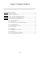
Chapter 1. Precautions for Safety This chapter describes precautions for using this product safely and properly. For precautions for the emulator main unit, the emulation pod main unit and the emulator debugger, refer to each user's manual included with your product. 1.1 Safety Symbols and Meanings ..................................................................................................... 8 WARNING Warning for Installation ........................................................................
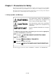
Chapter 1. Precautions for Safety In both the user's manual and on the product itself, several icons are used to insure proper handling of this product and also to prevent injuries to you or other persons, or damage to your properties. This chapter describes the precautions which should be taken in order to use this product safely and properly. Be sure to read this chapter before using this product. 1.
WARNING Warning for Installation: • Do not set this product in water or areas of high humidity. Spilling water or some other liquid into the main unit can cause an unrepairable damage. Warnings for Use Environment: • The emulation pod is air-cooled with the ventilation slot. Therefore, do not block the ventilation slot. When heated to high temperatures, the emulation pod may not work properly. • This equipment is to be used in an environment with a maximum ambient temperature of 35°C.
(1) Set the target system on a platform to relax bends and relieve stress in the board. (2) The boundary between the firm and flexible parts of the flexible board does not ready bend. Do not bend it excessively. When bending the flexible board, keep R to 30 mm or more as shown at left. Figure 1.1 Note on handling the flexible cable PCA7733 REV.
IMPORTANT Note on Malfunctions in the PC4701 System: • If the emulator malfunctions because of interference such as external noise, do the following to remedy the trouble. (1) Press the RESET button on the emulator front panel. (2) If normal operation is not restored after step (1), shut OFF power to the emulator once and then reactivate it.
IMPORTANT Note on Differences between Actual MCU and Emulator: • Operations of the emulator differ from those of mask MCUs as listed below. (1) Reset condition (2) Initial values of internal resource data at power-on (3) Interrupt stack pointer after releasing reset (4) Internal memory (ROM and RAM) capacities, etc. Therefore, be sure to evaluate your system with an evaluation MCU. Before starting mask production, evaluate your system and make final confirmation with an ES (Engineering Sample) version MCU.
IMPORTANT Note on Interruption: • While the program is paused, interrupts are made by running a selected address loop. For this reason, timers and other functions are not stopped while the program is paused (including while debug programs are running). If an interrupt request is generated at any time other than when the program is being executed (while the user program is paused or a debug program is running), the interrupt is not generated because the emulator disables interrupts.
MEMO ( 14 / 54 )
Chapter 2. Preparation This chapter describes the package components, the system configuration and the preparation for using this product for the first time. 2.1 Package Components ................................................................................................................... 16 2.2 Other Tool Products Required for Development ......................................................................... 16 2.3 Name of Each Part ..............................................................
Chapter 2. Preparation 2.1 Package Components This product consists of the following items. When unpacking, check to see if your product package contains all of these items. Package components Item Quantity M38000TL2-FPD emulation pod main unit 1 PCA7733 REV.
2.3 Name of Each Part PC4701 Emulation pod main unit (M38000TL2-FPD) Target system RESET, GND and Vcc cables with overcurrent protective circuits Host machine Figure 2.1 System configuration (1) Emulation pod main unit (M38000TL2-FPD) (3) Flexible cable for connecting target system (PCA7733 REV.B) (2) Connector for connecting the PC4701 (4) Probe direction converter board (28DP-WS, 32LCC-S) (5) RESET, GND and Vcc cables with overcurrent protective circuits Figure 2.
2.4 When Using the Emulator for the First Time If you have purchased this emulation pod newly, it is necessary to download the firmware. The download procedure is given in Figure 2.3. Before attempting to download the firmware, check the emulator debugger is installed and the emulator is connected to the host machine. For more information, see each user's manual of the emulator debugger and the PC4701. Connect the PC4701 and this product. See "3.3 Connecting the PC4701" (page 22).
Chapter 3. Setting Up This chapter describes switch settings required for using this product and how to connect this product to the PC4701 and the target system. 3.1 Switch Settings ............................................................................................................................ 20 3.2 Selecting Clock Supply ............................................................................................................... 21 3.3 Connecting the PC4701 ................................
Chapter 3. Setting Up With this product, it is necessary to set switches of the emulation pod and connect the RESET, GND and Vcc cables according to your target system. 3.1 Switch Settings The M38000TL2-FPD is designed for use with the RSS/RFS and RLSS/RLFS chips*1 in the 740 Family MCUs. The MCU type select switch (SW1) is used to switch the emulator MCU's operating supply voltage sense input and feeding supply voltage output via Vcc cable.
3.2 Selecting Clock Supply With this product, the oscillator circuit on the target system is always used to supply a clock to the MCU. To select the clock supply on the emulator debugger is invalid. IMPORTANT Note on Changing the Clock Supply: • With the M38000TL2-FPD, it is fixed to use the oscillator circuit on the target system as a clock supply. Make note of the fact that the setting by Init dialog when starting up the emulator debugger or inputting CLK command on the script window is invalid.
3.3 Connecting the PC4701 To connect the emulation pod to the PC4701, use the 120-pin flexible cable included with this product package. Connect the PC4701 side connector of the 120-pin flexible cable to the cable connector of the PC4701, then secure with screws. Figure 3.2 shows how to connect the PC4701 and 120-pin flexible cable. Figure 3.2 Connecting the PC4701 and cable CAUTION Note on Connecting the Cable: • Always shut OFF power before connecting the cable.
3.4 Connecting the Emulator MCU There are following three methods to connect the emulator MCU and M38000TL2-FPD, so you can choose the appropriate method depending on the type of an emulator MCU. (1) When the emulator MCU is an RSS or RLSS chip (2) When the emulator MCU is an RFS or RLFS chip with screw-lock (3) When the emulator MCU is an RFS or RLFS chip without screw-lock For methods (1) and (3), use the 28DP-WS board as the probe direction converter board; for method (2), use the 32LCC-S board.
(1) When Emulator MCU is an RSS or RLSS Chip If the emulator MCU is an RSS or RLSS chip, use the 28DP-WS board as the probe direction converter board to connect with the target system. When connecting, match the No. 1 pin of the 28DPWS, emulator MCU and target system. When using the 28DP-WS board, you can choose one of two methods of connection that is matched to the direction of the emulator MCU on the target system. Figure 3.5 shows each method of connection.
(2) When Emulator MCU is an RFS or RLFS Chip with Screw-lock If the emulator MCU is an RFS or RLFS chip with a screw-lock, use the 32LCC-S board as the probe direction converter board to connect with the target system. 32LCC-S Connecting procedure (1) Connect the RFS/RLFS chip with a screwlock to the MCU socket on the target system. (2) Connect the 32LCC-S to the RFS/RLFS chip with a screw-lock. (3) Connect the PCA7733 REV.B and the 32LCC-S. Make sure the polarity key is set properly.
(3) When Emulator MCU is an RFS or RLFS Chip without Screw-lock If the emulator MCU is an RFS or RLFS chip without a screw-lock, use the 28DP-WS board as the probe direction converter board and the PCA4933 (separately available) to connect with the target system. PCA7733 REV.B 28DP-WS Connecting procedure (1) Connect the 28DP-WS and the PCA4933. (2) Connect the PCA4933 to the RFS/RLFS chip without screw-lock. (3) Connect the PCA7733 REV.B and the 28DPWS.
3.6 M38000TL2-PSW (RESET, GND and Vcc Cables with Overcurrent Protective Circuits) The M38000TL2-PSW is an upgraded version of the RESET, GND and Vcc cables with protective circuits added for prevention of possible damage to the M38000TL2-FPD in case the cables are improperly connected. (1) Functions of Each Part of the M38000TL2-PSW Here following explains the function of each part of the M38000TL2-PSW. Figure 3.
(2) Connecting the M38000TL2-PSW to the M38000TL2-FPD TARGET WHITE: RESET YELLOW: VCC (SENSE) BLACK: GND Connect the M38000TL2-PSW to the M38000TL2-FPD. Connect the connector matching the color of the M38000TL2-PSW's each cable and the color display on the M38000TL2-FPD (see Figures 3.9 and 3.10). M38000TL2-FPD Connector for emulation pod White (RESET) Yellow (Vcc) Black (GND) Figure 3.9 Connecting the M38000TL2-FPD Figure 3.
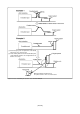
(3) Connecting the M38000TL2-PSW to the Target System Connect the clips for RESET, GND and Vcc on the tip of the M38000TL2-FPD's three-color cables to the RESET, GND and Vcc pins on the target system. (1) Reset cable (white) (2) GND cable (black) (3) Vcc cable (yellow) These three types of cables are connected differently depending on how the MCU type select switch (SW1) is set. Table 3.2 lists the SW1 settings and the connection of the RESET, GND and Vcc cables. Figures 3.11 and 3.
(4) LED Display The M38000TL2-PSW turns off the LED to alert you when Vcc and GND are mistakenly connected. The M38000TL2-PSW may become hot when Vcc and GND are mistakenly connected. If so, immediately turn off the power and check whether these pins are connected correctly. The LED does not go out when Vcc and RESET or GND and RESET are mistakenly connected.
Chapter 4. Usage This chapter describes from turning on the power of this product to starting up the emulator debugger. 4.1 Turning On the Power Supply ..................................................................................................... 32 (1) Checking the Connection of the System ............................................................................... 32 (2) Turning On the Power Supply ..............................................................................................
Chapter 4. Usage 4.1 Turning On the Power Supply (1) Checking the Connection of the System Before turning the power ON, check the connection of the PC4701, emulation pod, converter board and target system. (2) Turning On the Power Supply Power ON/OFF the target system and the PC4701 as simultaneously as possible. CAUTION Notes on Power Supply: • The emulator's VCC pin is connected to the target system in order to monitor target system voltage.
(3) LED Display When the PC4701 Starts Up Normally After the emulator starts up, check the status of the LEDs on the front panel to see whether emulation pod operation is enabled or not. Figure 4.1 shows front panel LED lighting status when the emulator is turned ON. When using M3T-PD38 V.3.00 Release 1 or later When starting up M3T-PD38 Started up normally after powered on When this does not light, check the power voltage of the target system. When using M3T-PD38 V.2.
4.2 Downloading Firmware (1) When It is Necessary to Download Firmware It is necessary to download firmware when: (1) you use this product for the first time (2) the firmware has been upgraded (3) the emulator debugger has been upgraded (4) you use this product with the PC4701 which was used with other emulation pod before (2) Downloading Firmware in Maintenance Mode Download the firmware in maintenance mode as explained here following.
4.3 Self-check (1) Self-check Procedure To run the emulator self-check, do so as explained here below. While the self-check is in progress, LEDs will change as shown in Figure 4.3. (1) Set the switches in the emulation pod same as the factory-setting (see "Table 3.1 Switch settings of the M38000TL2-FPD" on page 20). (2) Within 2 seconds of activating power to the emulator, press the RESET button on the emulator front panel to switch the emulator to maintenance mode.
Figure 4.
Chapter 5. Specifications This chapter describes specifications of this product. 5.1 Specifications .............................................................................................................................. 38 5.2 External Dimensions ................................................................................................................... 39 (1) External Dimensions of the Emulation Pod ..........................................................................
Chapter 5. Specifications 5.1 Specifications Table 5.1 lists the specifications of the M38000TL2-FPD. Table 5.1 Specifications of the M38000TL2-FPD Emulator PC4701 Applicable MCUs 740 Family MCUs which have an emulator MCU Usable modes Single-chip mode Memory expansion mode Microprocessor mode Emulation memory 64 KB Maximum operating frequency 16 MHz (Vcc = 5.0 V)*1 Applicable power voltage RSS/RFS type 2.0 - 5.5 V*2 RLSS/RLFS type*3 0.9 - 5.5 V*2 Stack capacity of emulator Max.
5.2 External Dimensions (1) External Dimensions of the Emulation Pod Unit: mm Figure 5.
(2) External Dimensions of the Converter Board (28DP-WS) Figure 5.2 shows the external dimensions of the converter board 28DP-WS for connecting the RSS type emulator MCU. D: 35.0 mm W: 18.0 mm H: 14.0 mm Figure 5.2 External dimensions of the converter board 28DP-WS (3) External Dimensions of the Converter Board (32LCC-S) Figure 5.3 shows the external dimensions of the converter board 32LCC-S for connecting the RFS type emulator MCU. D: 33.0 mm W: 25.0 mm H: 18.0 mm Figure 5.
Chapter 6. Troubleshooting This chapter describes how to troubleshoot when this product does not work properly. 6.1 Flowchart to Remedy the Troubles ............................................................................................. 42 (1) When the PC4701 is Not Powered On.................................................................................. 43 (2) When the LED Display of the PC4701 is Abnormal ............................................................
Chapter 6. Troubleshooting 6.1 Flowchart to Remedy the Troubles Figure 6.1 shows the flowchart to remedy the troubles from when power to the emulator is activated until emulator debugger M3T-PD38 starts up (Program Window displayed). Troubleshooting until the emulator system starts up Starting up the emulator (Turn ON the emulator and the target system simultaneously.) Can not power on Refer to "4.1 Turning On the Power Supply" (page 32) and PC4701 User's Manual.
(1) When the PC4701 is Not Powered On Table 6.1 Checkpoints when the PC4701 is not powered on Checkpoint Error The PC4701 can not be powered on. • Recheck the connection between the PC4701 and the power cable. See "4.1 Turning On the Power Supply" (page 32) and PC4701 User's Manual. (2) When the LED Display of PC4701 is Abnormal Table 6.2 LED's abnormal display and its checkpoints Checkpoint Error • Recheck the connection between the PC4701 and the power cable. LEDs do not light up. See "4.
(4) When the Program Window is Not Displayed Normally Table 6.3 Checkpoints of errors when starting up the emulator debugger Checkpoint Error The emulation pod is not connected to the • The emulator system and host are not communicating normally. target system. The emulation pod cannot be connected to the target system. Communication error occurred. Data was not sent to the target. Communication error occurred. Data was not received from the target. Target system cannot be properly built.
6.2 When an Error Message "Cannot be reset" is Displayed When an error message "Target MCU cannot be reset. Reset the target system." is displayed at the time of starting up the M3T-PD38, check the following: (1) The firmware does not match the emulation pod used.
6.3 When an Error is Detected in the Self-check Before starting the self-check, the emulator PC4701 check the status of the emulation pod, firmware and target system. When the self-check does not result normally, see "4.3 Self-check (2) If an Error is Detected in the Self-check" (page 35). With the emulator debugger M3T-PD38 V.3.00 Release 1 or later, the RESET LED remains on under normal conditions. The firmware in M3T-PD38 V.3.
6.5 FAQs Here following are frequently asked questions for using this product other than the troubles shown in the antecedent. For the latest FAQs, refer to the URL below. http://www.renesas.com/en/tools Q. 1 The maximum operating frequency of 3803 and 3804 Group MCUs is 16.8 MHz, yet the maximum operating frequency of the M38000TL2-FPD is 16.0 MHz. Does this emulation pod really operate at 16.8 MHz? A. 1 This emulation pod works at 16.
MEMO ( 48 / 54 )
Chapter 7. Maintenance and Guarantee This chapter describes how to maintenance, repair provisions and how to request for repair. 7.1 Maintenance................................................................................................................................. 50 7.2 Guarantee ..................................................................................................................................... 50 7.3 Repair Provisions ............................................................
Chapter 7. Maintenance and Guarantee 7.1 Maintenance If dust or dirt collects on any equipment of your emulation system, wipe it off with a dry soft cloth. Do not use thinner or other solvents because these chemicals can cause the equipment's surface coating to separate. 7.
7.4 How to Request for Repair If your product is found faulty, follow the procedure below to send your product for repair. Customer Fill in the Repair Request Sheet included with this product, then send it along with this product for repair to your local distributor. Make sure that information in the Repair Request Sheet is written in as much detail as possible to facilitate repair.
MEMO ( 52 / 54 )
M38000TL2-FPD User's Manual Rev.2.