
User manual


Rev. 1.00, 05/04, page 276 of 544
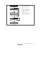
12.8.7 Switching from SCK Pins to Port Pins
When SCK pins are switched to port pins after transmission has completed, pins are enabled for
port output after outputting a low pulse of half a cycle as shown in figure 12.25.
SCK/Port
CKE0
CKE1
C/A
TE
Data
1. Transmission end
2. TE = 0
3. C/A = 0
4. Low pulse output
Bit 6
Bit 7
Low pulse of half a cycle
Figure 12.25 Switching from SCK Pins to Port Pins
To prevent the low pulse output that is generated when switching the SCK pins to the port pins,
specify the SCK pins for input (pull up the SCK/port pins externally), and follow the procedure
below with DDR = 1, DR = 1, C/A = 1, CKE1 = 0, CKE1 = 0, and TE = 1.
1. End serial data transmission
2. TE bit = 0
3. CKE1 bit = 1
4. C/A bit = 0 (switch to port output)
5. CKE1 bit = 0
SCK/Port
CKE0
CKE1
C/A
TE
Data
1. Transmission end
2. TE = 0
4. C/A = 0
3. CKE1 = 1
5. CKE1 = 0
Bit 6
Bit 7
High output
Figure 12.26 Prevention of Low Pulse Output at Switching from SCK Pins to Port Pins