
User manual


Rev. 1.00, 05/04, page 351 of 544
14.3 Register Descriptions
The keyboard buffer controller has the following registers for each channel.
• Keyboard control register H (KBCRH)
• Keyboard control register L (KBCRL)
• Keyboard data buffer register (KBBR)
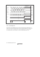
14.3.1 Keyboard Control Register H (KBCRH)
KBCRH indicates the operating status of the keyboard buffer controller.
Bit Bit Name
Initial
Value R/W Description
7 KBIOE 0 R/W Keyboard In/Out Enable
Selects whether or not the keyboard buffer controller is
used.
0: The keyboard buffer controller is non-operational
(KCLK and KD signal pins have port functions)
1: The keyboard buffer controller is enabled for
transmission and reception (KCLK and KD signal
pins are in the bus drive state)
6 KCLKI 1 R/W Keyboard Clock In
Monitors the KCLK I/O pin. This bit cannot be modified.
0: KCLK I/O pin is low
1: KCLK I/O pin is high
5 KDI 1 R/W Keyboard Data In:
Monitors the KDI I/O pin. This bit cannot be modified.
0: KD I/O pin is low
1: KD I/O pin is high
4 KBFSEL 1 R/W Keyboard Buffer Register Full Select
Selects whether the KBF bit is used as the keyboard
buffer register full flag or as the KCLK fall interrupt flag.
When KBFSEL is cleared to 0, the KBE bit in KBCRL
should be cleared to 0 to disable reception.
0: KBF bit is used as KCLK fall interrupt flag
1: KBF bit is used as keyboard buffer register full flag