
User manual


Rev. 1.00, 05/04, page 369 of 544
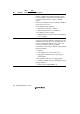
15.2 Input/Output Pins
Table 15.1 lists the input and output pins of the LPC module.
Table 15.1 Pin Configuration
Name Abbreviation Port I/O Function
LPC address/
data 3 to 0
LAD3 to
LAD0
P33 to
P30
Input/
output
Serial (4-signal-line) transfer cycle
type/address/data signals,
synchronized with LCLK
LPC frame LFRAME P34 Input*
1
Transfer cycle start and forced
termination signal
LPC reset LRESET P35 Input*
1
LPC interface reset signal
LPC clock LCLK P36 Input 33 MHz PCI clock signal
Serialized interrupt request SERIRQ P37 Input/
output*
1
Serialized host interrupt request
signal, synchronized with LCLK
(SMI, IRQ1, IRQ6, IRQ9 to
IRQ12)
LSCI general output LSCI PB1 Output*
1,
*
2
General output
LSMI general output LSMI PB0 Output*
1,
*
2
General output
PME general output PME P80 Output*
1,
*
2
General output
GATE A20 GA20 P81 Output*
1,
*
2
A20 gate control signal output
LPC clock run CLKRUN P82 Input/
output*
1,
*
2
LCLK restart request signal in
case of serial host interrupt
request
LPC power-down LPCPD P83 Input*
1
LPC module shutdown signal
Notes: 1. Pin state monitoring input is possible in addition to the LPC interface control
input/output function.
2. Only 0 can be output. If 1 is output, the pin goes to the high-impedance state, so an
external resistor is necessary to pull the signal up to V
CC
.