
User manual


Rev. 1.00, 05/04, page 464 of 544
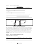
20.1.1 Standby Control Register (SBYCR)
SBYCR controls power-down modes.
Bit Bit Name
Initial
Value
R/W Description
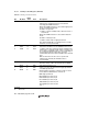
7 SSBY 0 R/W Software Standby
Specifies the operating mode to be entered after
executing the SLEEP instruction.
When the SLEEP instruction is executed in high-speed
mode or medium-speed mode:
0: Shifts to sleep mode
1: Shifts to software standby mode, subactive mode, or
watch mode
When the SLEEP instruction is executed in subactive
mode:
0: Shifts to subsleep mode
1: Shifts to watch mode or high-speed mode
Note that the SSBY bit is not changed even if a mode
transition occurs by an interrupt.
6
5
4
STS2
STS1
STS0
0
0
0
R/W
R/W
R/W
Standby Timer Select 2 to 0
Selects the wait time for clock stabilization from clock
oscillation start when canceling software standby mode,
watch mode, or subactive mode. Select a wait time of 8
ms (oscillation stabilization time) or more, depending on
the operating frequency. Table 20.1 shows the
relationship between the STS2 to STS0 values and wait
time.
With an external clock, there are no specific wait
requirements. Normally the minimum value is
recommended.
3 0 R Reserved
This bit is always read as 0, and cannot be modified.
2
1
0
SCK2
SCK1
SCK0
0
0
0
R/W
R/W
R/W
System Clock Select 2 to 0
Selects a clock for the bus master in high-speed mode
or medium-speed mode.
When making a transition to subactive mode or watch
mode, SCK2 to SCK0 must be cleared to 0.
000: High-speed mode
001: Medium-speed clock: φ/2
010: Medium-speed clock: φ/4
011: Medium-speed clock: φ/8
100: Medium-speed clock: φ/16
101: Medium-speed clock: φ/32
11X: —
[Legend]
X: Don't care